background image

© 2021 Carrier 


16 

FLAME SCANNERS 

INSTALLATION - UV SCANNERS

Where possible, obtain the burner manufacturer’s instructions for mounting the scanner. This infor- 
mation is available for most standard burners. The scanner mounting should comply with the follow- 
ing general instructions: 
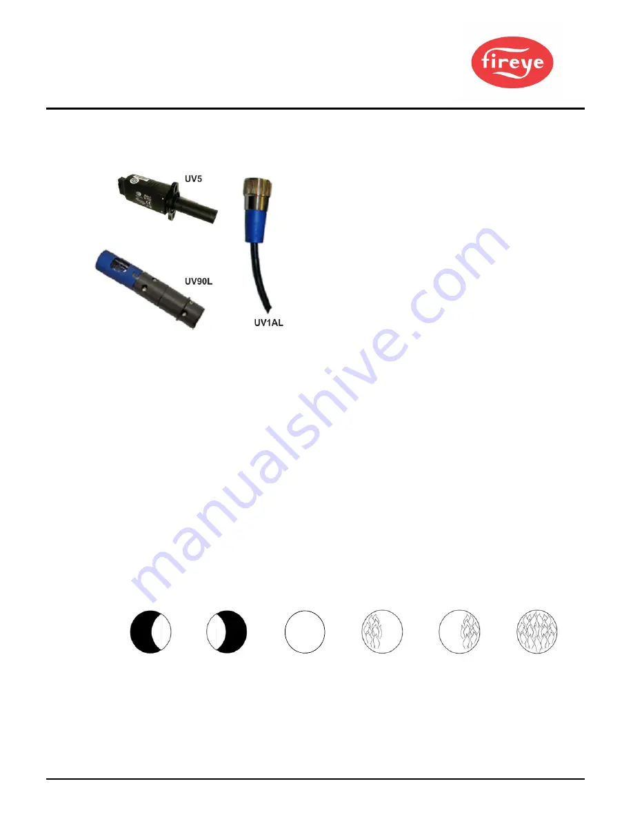
1. 

Position  the  UV1AL,  UV90L or  UV5  scanner  within  39  inches  (1  meter)  of  the  flame  to  be 
monitored. 

2.

Select a scanner location that remains within the ambient temperature limits of the UV scanner. 

3.

The UVlAL scanner is designed to seal off the sight pipe up to 1 PSI pressure. Higher furnace 
pressures must be sealed off. To seal off positive furnace pressure up to 50 PSI for the UV1AL 
scanner, install a quartz window coupling (P/N: 60-1257). Add cooling air to reduce the scanner 
sight pipe temperature. 

4.

Install the scanner on a standard NPT pipe (UV1AL: ½”) whose position is rigidly fixed. If the 
scanner mounting pipe sights through the refractory, do not extend it more than halfway through. 
Swivel flanges are available if desired (P/N: 60-302). The sight pipe must permit an unobstructed 
view of the pilot and/or main flame, and both pilot and main flames must com- pletely cover the 
scanner field of view. 

SCANNER MUST  HAVE UNOBSTRUCTED 

VIEW  OF FLAME

NOT THIS 

NOT THIS 

BUT THIS

FLAME MUST  COMPLETELY COVER 

SIGHT OPENING

NOT THIS 

NOT THIS 

BUT THIS

Summary of Contents for 60-2991 Series

Page 1: ...mote reset via line voltage input Smart LEDs that provide operational sequence lockout information and flame intensity Modbus RTU communication via RS485 with read write capability Small footprint 4 15 105mm L x 4 15 105mm W x 5 0 127mm H Expert support from the Fireye team This manual describes the installation commissioning operation and maintenance of the 60 2991Wiring Harness It may be used in...

Page 2: ... limits interlocks actuators valves transformers motors and other devices are operating properly Such tests must be conducted with manual fuel valves in the closed position only Replace all limits and interlocks not operating properly and do not bypass limits in interlocks Failure to follow these guidelines may result in an unsafe condition hazardous to life and property TABLE OF CONTENTS APPLICAT...

Page 3: ...40 standard version Control Dimensions With wiring base 60 2981 1 or 2 4 15 L x 4 15 W x 5 0 H 105mm x 105mm x 127mm Shipping Weight Approx 1 3 lbs 0 6 kg Relative Humidity 90 R H Non Condensing OPERATING TEMPERATURE LIMITS CONTROL MAXIMUM MINIMUM BP110 140 F 60 C 40 F 40 C UV90L 1 194 F 90 C 40 F 40 C UV1AL 3 6 200 F 94 C 40 F 40 C UV5 1 UV5 2 140 F 60 C 4 F 20 C LOAD RATINGS Terminal Typical Loa...

Page 4: ...ratings are intended for motors VA and VA pilot duty loads may be added to a motor load provided the total load does not exceed the published rating OPERATIONAL TIMINGS The BurnerPRO is pre programmed from the factory with a set of operational timings necessary for the safe operation of the burner system However operational timings can be modified via the Modbus port using the 60 3000 ModBus Comms...

Page 5: ... Controls Primary Safety File MCCZ7 MP1537 Controls Primary Safety Certified for Canada PART NUMBERS AND APPROVALS Table 1 Agency Approvals Fireye Part Number 60 2991 1 X 60 2991 2 X BP110UVFR S11M X BP110UVFR S12M X BP110UVFR S13M X BP110UVFR S14M X X CERTIFICATION IN HAND ...

Page 6: ... 4 742 1 Replacement tube for UV90L 1 UV1AL CEX Cenelec Exd IIC explosion proof housing with UV1AL 3 scanner INSTALLATION PROCEDURE WARNING Disconnect power supply before beginning installation to prevent electrical shock and equipment damage More than one disconnect may be involved 1 A UL listed flame safeguard system is comprised of the following items a 60 2991 1 or 60 2991 2 wiring harness b B...

Page 7: ...o follow these instructions can cause a hazardous condition and or equipment damage 10 Before installation ensure that the control is suitable for your application by verifying all ratings and functionality 11 After installation verify all control operation as provided in these instructions Published load ratings assume that the internal contacts will only get switched once every 15 seconds Using ...

Page 8: ...Fire Start Switch 15 3 Alarm 3 12 High Fire Internal relays 4 13 Common Internal relays 4 14 Low Fire Internal relays 4 15 Auto Internal relays 4 22 Shutter Not used 1 Terminal 4 is internally jumpered to terminal 1 via the BurnerPro control 2 If the Honeywell control used a non self check UV scanner then the Honeywell scanner must be removed and the Fireye UV scanner must be wired into terminals ...

Page 9: ...ed a non self check UV scanner then the Honeywell scanner must be removed and the Fireye UV scanner must be wired into terminals 22 and 23 on the BurnerPro wiring base 3 The BurnerPro will lockout when the Running Safety Interlock circuit opens Jumper JR3 on the RM7895 selects recycle or lockout 4 Terminal 17 on the BurnerPro provides interrupted operation of the pilot fuel valve If intermittent o...

Page 10: ...per JR1 clipped 4 sec PTFI 18 Intermittent Pilot Existing Honeywell RM7800L Installation Action Firing Natural Gas Light Oil Ignition Pilot on Term 8 Use S11M with defaults Firing Heavy Oil Ignition Pilot on Term 21 JR intact Use S12M with defaults Move wire from Term 21 to Term 8 on Honeywell wiring base Firing Heavy Oil Ignition Pilot on Term 21 JR clipped Use S12M Change TSA TSA to 5 sec Move w...

Page 11: ...neywell RM7800G Installation Action Firing Natural Gas Light Oil Ignition Pilot on Term 8 Use S11M with defaults Jumper Term 4 to 19 on MH wiring base Firing Heavy Oil Ignition Pilot on Term 21 JR1 intact Use S12M with defaults Move wire from Term 21 to Term 8 on Honeywell wiring base Jumper Term 4 to 19 on Honeywell wiring base Firing Heavy Oil Ignition Pilot on Term 21 JR1 clipped Use S12M Chang...

Page 12: ...Oil Ignition on Term 8 Pilot on Term 21 JR1 intact Use S11M with defaults move wire from MH Term 8 to Term 10 Jumper Term 8 to 21 on MH wiring base Jumper Term 4 to 18 19 on Honeywell wiring base Firing Natural Gas or Heavy Oil Ignition on Term 10 Pilot on Term 21 JR1 clipped Use S11M with defaults set TSA TSA to 5 sec Jumper Term 8 to 21 on MH wiring base Jumper Term 4 to 18 19 on Honeywell wirin...

Page 13: ...in fuel piloted 5s 5s 5s 5s t4 Interval between start of TSA and the main fuel piloted 5s 5s 5s 5s t5 Interval between main fuel piloted and release to modulation 15s 15s 15s 15s t6 Post purge time 15s 15s 5s 5s t7 Pilot stabilization period 0s 0s 0s 0s t9 Interval between main fuel piloted and removal of pilot MTFI 10s 14 9s 10s 14 9s t11 Air damper running time to the high fire position Optional...

Page 14: ... 2021 Carrier 14 ...

Page 15: ... 2021 Carrier 15 ...

Page 16: ...er furnace pressures must be sealed off To seal off positive furnace pressure up to 50 PSI for the UV1AL scanner install a quartz window coupling P N 60 1257 Add cooling air to reduce the scanner sight pipe temperature 4 Install the scanner on a standard NPT pipe UV1AL whose position is rigidly fixed If the scanner mounting pipe sights through the refractory do not extend it more than halfway thro...

Page 17: ...TIONS WIRING UV SCANNERS To connect the scanner to the control the UV1AL scanner is supplied with UV1AL 3 36 or UV1AL 6 72 0 9 m or 1 8 m of flexible cable The UV90L is supplied with a terminal board Use two 18 AWG conductors to connect the UV90L to the control The UV5 is supplied with 80 2m of flexible cable detachable If it is necessary to extend the scanner wiring the following instructions app...

Page 18: ...If the flame is partly luminous the electrode tip must extend only to the edge of the flame It is not necessary to maintain uninterrupted contact with the flame 6 It is preferable to angle the rod downward to minimize the effect of sagging and to prevent it from coming in contact with any object 7 An adequate grounding surface for the flame must be provided The grounding surface in actual contact ...

Page 19: ...h equipment manufactured by others and or integrated into systems designed or manufactured by others the Fireye warranty as stated in its General Terms and Conditions of Sale pertains only to the Fireye products and not to any other equipment or to the combined system or its overall performance WARRANTIES FIREYE guarantees for one year from the date of installation or 18 months from date of manufa...

Reviews: