10
HotPort 7000 Series Mesh Nodes
September 2010
Connecting Cables
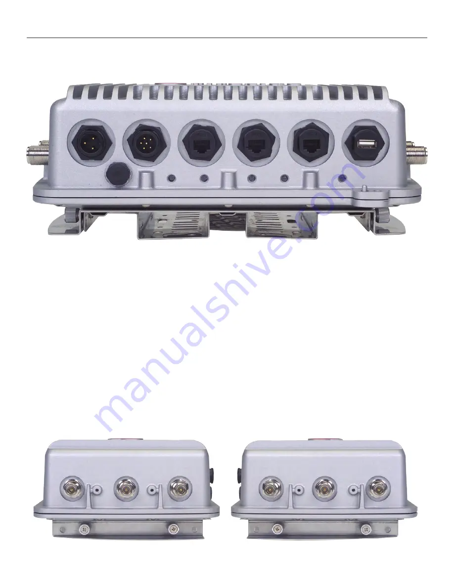
After your node is mounted, attach the six antennas, the power cable, and any Ethernet cables you need. Note that all of the weath-
erproof caps have been removed from the node for illustrative purposes. You should not leave any unused connector uncovered.
Figure 5. HotPort 7020 Bottom Panel
port 1
port 2
port 3
dc power
usb
ac power
power
status
radio 1
radio 2
ethernet
–mesh–
Note the locations of the reset button under the weatherproof cap. To reset the unit, apply power and wait until the unit has fully
booted and the status light has come on. Then use a paperclip to press and hold the reset button until the status LED blinks.
Power Connection
Connect the suppled AC power cable to AC power and to the HotPort node. If you wish to power your node with DC power, you will
need a source of power which can deliver 12 V ±10% at 3 A. Information on building custom power cables is shown in Appendix B. Do
not connect both AC and DC supplies simultaneously.
Powering Other Ethernet Devices
Ports 2 and 3 on a Series 7020 node can provide Power over Ethernet (PoE) functionality to Powered Devices (PD) connected to these
ports. (Port 1 cannot.) A Powered Device can receive data and the power to process the data from the HotPort node, which functions as
Power Sourcing Equipment (PSE) in this configuration. To receive power from a HotPort node, the device must support the IEEE 802.3af
standard, which defines PoE functionality.
Connecting Antennas
Don’t forget to order your permanent outdoor antennas! You can’t use the staging antennas outdoors, they might fail.
When connecting antennas, connect them in numerical order 1-2-3. If you are not using three antennas per radio, do not ‘skip’ antenna
connectors. The antenna 1 connector is at the top of the unit (farthest from the power and Ethernet connections) on both the left
and right side.
antenna 2
antenna 1
antenna 3
radio 1
antenna 2
antenna 3
antenna 1
radio 2


