


Service Manual 0-2692
15
Firepower FP-18 Plasma Cutter
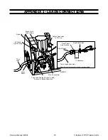
4.5 Air Compressor
Replacement
NOTES
Refer to subsection 4.1, General Information, for
information about wire harnesses.
Refer to Appendix II for parts location and orien-
tation.
1. Remove cover/handle from unit per subsection 4.2.
2. Locate the nylon nut on the 90° nylon fitting on
side of Air Compressor. Loosen the nylon nut and
slide the brass torch lead fitting/faston connector
out.
3. Complete one of the following, as it pertains to
your unit:
• Rev C units or earlier - Disconnect black wire
from Compressor to faston splice & wire #21.
Disconnect red wire from Compressor to up-
per diode piggy back terminal.
• Rev D units or later - Disconnect black wire from
Compressor to faston splice & wire #29. Dis-
connect red wire from Compressor to upper di-
ode piggy back terminal.
4. Slide Compressor out of bracket.
5. Note position and angle of 90° nylon nut connected
to the Air Compressor. Remove fitting.
6. Clean old teflon thread sealant from nylon fitting,
apply new thread sealant and install nylon fitting
on replacement Air Compressor. Make sure fit-
ting is in proper position.
7. Remove "feet" from Compressor and install on re-
placement Compressor.
8. Insert replacement Air Compressor into bracket,
insuring "feet" have dropped into slots in bracket.
9. Apply a small amount of O-Ring lubricant to brass
torch fitting and insert into 90° nylon fitting.
Tighten nylon nut.
NOTE
Be careful not to remove the nylon nut completely
as there are small parts inside that could fall out.
10. Connect the following as it pertains to your unit:
• Rev C units (or earlier) - Connect black wire
from Compressor to faston splice & wire #21.
Connect red wire from Compressor to upper
diode piggyback terminal.
• Rev D units (or earlier) - Connect black wire
from Compressor to faston splice & wire #29.
Connect red wire from Compressor to upper
diode piggyback terminal.
11. Position wire connector L4 so that it runs along
side the Transformer, NOT across the top of the
Transformer.
12. Install cover/handle by reversing steps in sub-
section 4.2, keeping in mind the following:
a. The Air Compressor is secured in position by
one of the handle screws on the top side of the
power supply. Make sure that no wires ob-
struct the cover when it is installed.
4.6 Capacitor Replacement
WARNING
Disconnect primary power to the system before dis-
assembling the torch, leads, or power supply.
NOTE
Refer to subsection 4.1, General Information, for
information about wire harnesses.
1. Remove cover/handle from unit per subsection 4.2.
2. Make note of all wire connections and locations to
Capacitor.
3. Remove all wire connections to Capacitor.
4. The Capacitor is held in place by a tab located on
the Transformer frame. Using a screw driver or
similar tool, pry the tab back slightly to allow the
Capacitor to slide out of the bracket.
5. Install replacement Capacitor, by reversing steps
1-4, keeping in mind the following:
a. Make sure the Capacitor is securely positioned
behind tab. Tab may need to be bent.
b. Position wire connector L4 so that it runs along
side the Transformer, avoiding contact with
metal parts.
Summary of Contents for FP-18
Page 2: ......
Page 29: ...Service Manual 0 2692 25 Firepower FP 18 Plasma Cutter ...
Page 32: ......


