


15
3.
Wiring the FM –
To wire an e-match to the FM, strip both wires from the e-match and insert
each into the spring terminals in the respective slot of the FM. The orientation of the wires
does not matter, but we recommend that the end of the wire be stripped back about one inch
(25mm) and given a U bend to provide better contact with spring terminals. The numbers
below the spring terminals correspond to the channel for that slot. If the continuity test has
been turned on at the CM, press the CT button to see the continuity test results on the FM
screen.
4.
Continuity Test –
Select the CT button to go to the Continuity Test Page. When the CM is in
Continuity Test mode and the test is activated the FM’s LEDs will change to either Blue,
Magenta or Yellow. If the backlight LEDs are Blue, there are no shots detected. If the backlight
LEDs are Magenta, the FM is detecting one or more shots loaded. If the backlight LEDs are
Yellow, the FM is detecting that the continuity test system has failed an internal safety test
and is not sending the test current through the firing pins. If this happens contact Firelinx
support through www.firelinx.com. The screen will also display the following icons to show
the status of each channel:
•
= means that there is a loaded shot that is currently in the choreography on that pin.
•
? means that there is a loaded shot that is currently NOT in the choreography on that
pin.
•
X means that there is not a shot loaded but is currently in the choreography on that
pin.
•
* means that there is more resistance than expected on the pin, there might not be
enough energy to reliably fire every shot on that line.
5.
Armed –
If the module’s backlight LEDs are RED the module is armed and ready to fire.
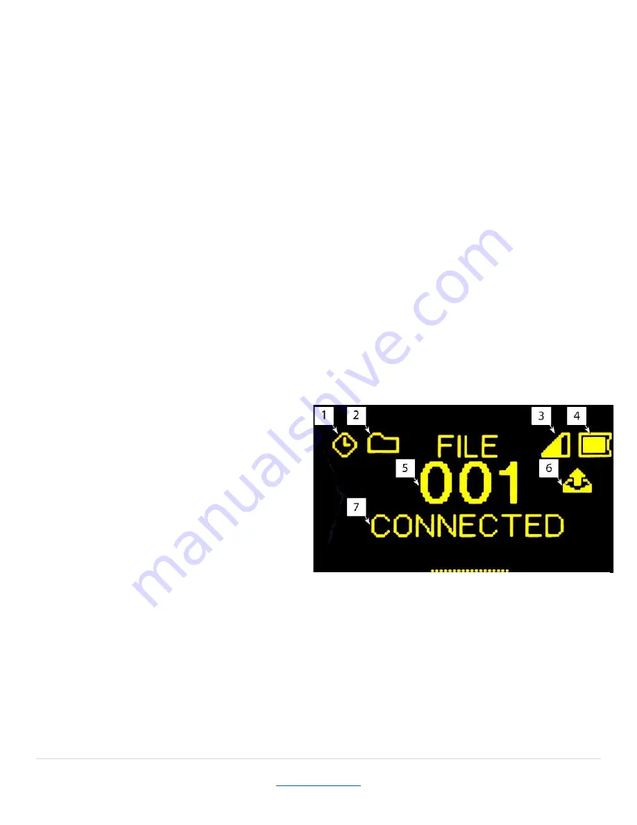
Home Page
1.
The clock in the top left corner of the
screen is displayed when the FM is
currently connected and synchronized
to the CM.
2.
The folder icon displays if there is a file
currently downloaded into the FM. If the
folder is dashed with an X there is no
file currently downloaded. The title of
the screen will read MANUAL instead of
FILE
3.
This icon displays the current signal
noise in the area, a high bar will display in a low noise area. If the bar is low move the FM to
a different area with a higher bar.
4.
This icon displays the current battery level of the FM.
5.
This displays the Name ID of the FM. All FMs must have unique Name IDs.
6.
This icon displays if the FM is firing a shot due to choreography. This icon will be preserved
on the screen until the next ARM cycle, so that the operator can check the “Has Fired” status
before, during, and after the show.
7.
This displays any messages generated by the FM system, such as if the FM is currently
connected or disconnected.
Pressing the down arrow will display the current software version installed on the FM.
Figure 21


