background image

REV. 4-13-16  Page 6

REQUIREMENTS

1.  Only non-combustible materials should come in direct contact with any part of the fire pit. Underneath area should be non-   

     combustible or a flat level combustible surface according to the clearances specified in this manual.
2.   

We recommend using ¾” black iron pipe; however please refer to the NFPA54 (National Fuel Gas Code) for proper  

       pipe sizing when exceeding 20-feet in length for fire pits rated above 100,000 BTU.

3.   Determine the size linear fire pit you are preparing to install (Refer to page 4).
4.   You must provide a rectangular cut out to place the fire pit into the non-combustible enclosure. 
5.   Follow the local code requirements for the gas type being used. This fire pit should be installed in accordance with           

      local codes and ordinances or in the absence of local codes, with the latest National Fuel Gas Code, ANSI Z223.1           

       NFPA54 or CSA B149.1, Natural and Propane Installation Code in Canada.
6.   Fire pits create high temperatures, it is very important to have any combustibles at a safe distance. 
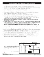
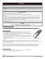
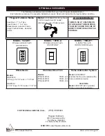
7.   Normal operation of the fire pit is with a battery pack that is supplied with your system (Fig 7). The battery pack has        

      12-feet of black sleeved wire that is to be passed through the junction box provided. This wire should not be cut or  

      spliced and the junction box can be placed in the facing of the vertical finish of the fire pit, if you place the wire under  

      ground you should install those wires into an approved protective conduit/sleeve material.
8.   Fire pit should never be left unattended while in operation. It should always be a safe distance from all trees and                         

     combustible landscape materials. 
10.  Construction of the finished fire pit should be stable and solid. From the bottom of the burner housing (cradle) that holds   

       the burner assembly it requires a minimum if of 15-inches to the ground level. See page 3. Drainage is critical to ensure  

       that water does not damage gas valve and components. Never install the fire pit system below grade.
11.  

CAUTION: The fire pit enclosure MUST have a minimum ventilation of 18 square inches on each side of the            

       finished enclosure.

12.  Never fill the cavity under and around the valve box with any material, this is a provided air space necessary for  


       ventilation. 
13.  These products are designed for outdoor use only. They are not approved for any indoor use. 
14.  This fire pit is designed for use with the following Firegear Outdoors media:  FG-Lava Rock (min. 1” diameter), FG-Lava   

       Stones, Firegear Liquid Glass Beads or Firegear Large Broken Glass. Cover the burner completely, so that the burner is  

       not highly visible. Do not cover more than 1” above the top of the burner screen.  
15.  Gas lines and fittings must be installed into the non-combustible structure. All gas connections must be leak tested          

       following installation of the fire pit. Soapy water leak detection is required before regular use of the fire pit.
16.  Do not use burner media (rocks/glass) that will absorb moisture over time and will not release this moisture quickly.          

       Moisture can boil in this material and can rapidly break apart and cause damage or personal injury.
17.  Never leave any other combustible material on top of the fire pit. This could cause unsafe operation of this system           

       and damage to the component that will not be covered under our warranty.

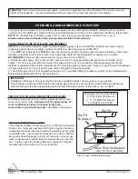
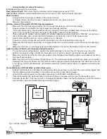
INSTALLATION OF FIRE PIT INTO AN APPROVED ENCLOSURE

Gas Supply

Fire Pit Pan

Non-Combustible 

Fire Pit Enclousure

Valve Box

Steel

  Studs

NOTE

:  Gas valve, flexible gas lines and TFS 

components are supplied.  A gas shut-off 

before the appliance is recommended but 

not supplied

Fig. 6  Typical installation.

TFS Linear Fire Pits

Summary of Contents for FPB-24LTFS-N

Page 1: ...For Outdoor Use Only PLEASE RETAIN THIS MANUAL FOR FUTURE REFERENCE INSTALLATION PRECAUTION This fire pit requires a minimum 18 square inches per side of cross ventilation Failure to provide proper ventilation can void the warranty MODELS Natural Gas Description Propane FPB 24LTFS N 24 Linear Pan Burner FPB 24LTFS P FPB 30LTFS N 30 Linear Pan Burner FPB 30LTFS P FPB 36LTFS N 36 Linear Pan Burner F...

Page 2: ...r appliances Any LP cylinder not connected for use shall not be stored in the vicinity of this or other appliances WARNING Do not leave unattended during use Do not use for cooking Follow all gas leak procedures in this manual prior to operation WARNING Improper installation adjustment alteration service or maintenance can cause injury of property damage Read the installation operating and mainten...

Page 3: ...a such as i e lava rock lava stones lava boulders has the potential of thermal spalling This is a process that may occur when media is wet and moisture gets trapped inside of the material due to rapid temperature differences When this happens the media has the potential to crack or pop outside the fire feature WE HIGHLY RECOMMEND COVERING ALL FIRE FEATURES WHEN NOT IN USE The use of a cover can le...

Page 4: ... proper gas pipe sizing will also affect BTU As a result your BTU may vary slightly from Table 2 specifications Fig 1 Fire Pit dimensions refer to Table 1 Pressure NG LP Min Inlet 5 0 WC 10 5 WC Max Inlet 10 5 WC 13 0 WC Normal Inlet 7 0 WC 11 0 WC Table 3 Gas Pressures Model Natural Gas NG Model Propane Gas LP A Pan Depth B Min Install Length C Burner Tube D Floor Level E Side Wall F Combustible ...

Page 5: ...the cradle brackets Each cradle bracket can be adjusted 1 2 from the top edge of the cradle or lowered to a total of 2 3 4 from the top edge of the cradle There are 1 4 increments to adjust the depth of the fire pit to fit most finishing materials See Fig 4 3 Pilot Covers are decorative spacers that provide equal spacing for all models One side is used as a pilot shield for the pilot system in the...

Page 6: ...hut off valve at the exterior house wall If pipe is to pass through a foundation or house wall make sure to re seal the area around the pipe with weather sealant 3 The primary gas shut off not supplied will require a male flared fitting to enable connection of the stainless steel flex gas line supplied with the fire pit see figure 4 IMPORTANT Installation of Natural or LP gas should be done by a q...

Page 7: ...rom the bottom of the burner housing cradle that holds the burner assembly it requires a minimum if of 15 inches to the ground level See page 3 Drainage is critical to ensure that water does not damage gas valve and components Never install the fire pit system below grade 11 CAUTION The fire pit enclosure MUST have a minimum ventilation of 18 square inches on each side of the finished enclosure 12...

Page 8: ...ll white screws provided Batteries can be changed or installed by removing the two screws that hold the cover plate battery pack in place Remove assembly slide cover away from the cover plate and install the 4 four AA batteries 6 Be sure the batteries are installed positive to positive and negative to negative If one battery is installed wrong the system will not operate 7 Once the fire pit is ins...

Page 9: ... See Fig 10 The cover will slide down exposing the gas valve and control module 2 Find the black module attached to the inside of the control box Locate the Learn Button on the bottom of the module 3 Once the Learn button is located press and release the button once You will hear a beep indicating that the module is ready to receive a transmitter code See Fig 11 4 Take the transmitter and press th...

Page 10: ...STALLING PILOT COVER AND PILOT SHIELD Final preparations will require you to install the pilot cover and pilot shield They are wrapped in a protective material to prevent scratches and are inside the carton of the fire pit After you fire tested the fire pit unwrap the pilot cover and pilot shield The pilot cover will sit into place inside each end of the cradle The pilot shield then slides into th...

Page 11: ...urn any solid fuels in this appliance LIGHTING INSTRUCTIONS NOTE It may take several cycles of ON OFF to purge the airflow from the gas lines The direct spark ignition will turn OFF after 20 seconds if the burner does not light after which you will need to press transmitter OFF button then back ON to initiate ignition again Flame height can be adjusted HI and LO After the fire pit is operating pre...

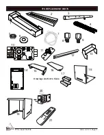
Page 12: ...OWER Learn AUX 13 14 AA Batteries AA Batteries AA Batteries AA Batteries 17 19 Latching Solenoid DC Moror Drive Requires 4 AA 1 5V alkaline batteries Control Box Battery cover slides on off Slide Switch ON OFF 20 5 7 LOW HI OFF ON 21 10 OUT PILOT ADJ IN MAIN PILOT 3 4 11 12 15 16 18 TFS Linear Fire Pits ...
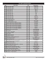
Page 13: ...lenoid 1 AF 4025DSILSS36 11 Pilot Assembly 1 PILOTO23300 206 12 Linear Burner Cradle Bracket 2 CRADLEBRACKET L 13 Linear Burner Ext Bracket 1 EXTBRACKET L 14 Ignition Module 1 VCS 5000MODTC 15 Linear Burner Pilot Shield 2 PILOTSHIELD L 16 Linear Burner Pilot Cover 2 PILOTCOVER L 17 AA Batteries 1 5 Volt used in battery pack 4 BATTAA 18 Valve Box Stainless Steel Lid 1 FIREPITMETALBOXCO 19 Valve Box...

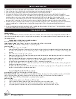
Page 14: ... users if the pilot is not successfully ignited in 20 seconds How to Clear Press OFF then ON buttons to re attempt ignition What to Check 1 Ensure gas supply is turned ON 2 Ensure that the gas line is purged of air Air is common in the gas line if the appliance has just been installed has been disconnected then re connected to the gas line or if the appliance has been unused for an extended period...

Page 15: ...r Sparks at Pilot Hood Frequently During Operation 1 The control module will generate a spark at the ignitor electrode to the pilot hood if the system is in the ON position but does not does not light thermocouple may not be hot enough or generating enough millivolts 2 Make sure that the tip of the thermocouple is clean Soot buildup will insulate the thermocouple and will not allow for proper flam...

Page 16: ...s the use of battery power LP CONVERSION KIT THERE IS NO LP CONVERSION KIT AVAILABLE THESE MODELS YOU MUST ORDER THE FIRE PIT DIRECT FROM THE FACTORY AS PROPANE MODEL 1322 WT Wireless wall switch with ON OFF HI LO MODEL 1001D A Wireless wall switch with ON OFF ONLY MODEL TMR AF1 4 Button Timer with 30 60 120 OFF Minutes Windshields Models GSW 3812 38 long x 12 7 8 wide x 7 1 2 tall GSW4312 43 1 2 ...

Page 17: ... cost service labor to repair the defect and freight charges on warranty parts to and from the factory will be responsibility of the owner We will not be responsible for labor charges and or damage incurred in installation repair and replacement This Limited Warranty is voided if not assembled installed and operated as intended This Limited Warranty does not cover any defects due to accident abuse...

Page 18: ..._____________ 2 Serial Number ___________________________ 3 How long is the gas line run Nat Gas ____ LP Gas ____ 4 What size is gas line _____ 5 Inlet Gas Pressure _____WC Manifold Gas Pressure _____ WC 6 What type of media are you using __________________ 7 Review the troubleshooting section in the installation manual 8 What are the symptoms Please be prepared to explain 9 Be prepared to send ph...

Reviews: