background image

REV. 10-10-12  Page 9

CAUTION

: Children and adults should be alerted to the hazards on high surface temperatures and should stay away to 

avoid burns or clothing ignition. Young children should be carefully supervised when they are in the area of the appliance.

WARNING:

 Do not use this appliance if any part has been under water. Immediately call a qualified service technician 

to inspect the appliance and to replace any part of control system and any gas control, which has been under water.

OPERATION 

SAFETY WARNINGS

 1.  Never leave the Fire Pit unattended during operation. 

 2.  Clothing or other flammable materials should not be placed on or near the appliance.   

 3.  Any guard or other protective device removed for servicing the appliance must be replaced prior to operating the  


     appliance.

 4.  Installation and repair should be done by a qualified service person. The appliance should be inspected before  


     use and at least annually by a qualified service person. More frequent cleaning may be required as necessary. It  


     is imperative the control compartment, burners and circulating air passageways of the appliance be kept clean.

 5.  Inspect the fuel supply connection before each use of the appliance.

 6.  Temporary storage of this appliance indoors is permissible only if it has been disconnected from its fuel supply      


      (Natural or L.P. gas line).

WARNING

1. This appliance is 

hot

 when operated and can cause sever burns if contacted.

2.  Do not burn any solid fuels in this appliance.

INITIAL START UP

1. Turn gas ON.  Ensure you have leak tested the fire pit before operating.

2. If using the optional 120V power adapter, you must turn the switch or breaker ON. If using the standard battery   

     pack, ensure batteries are installed and the Fire Pit is ready to operate. 

3. Press the ON button on the handheld transmitter.  You will hear the ignitor probe sparking, light the gas and fire  

    pit will come on.  WARNING: Do not stand over Fire Pit during ignition or operation due to high surface tempera  

    tures. 

NOTE

: It may take several cycles of ON/OFF to purge the airflow from the gas lines.  The direct spark ignition  


will turn OFF after 15 seconds if the burner does not light after which you will need to press transmitter OFF button then 

back ON to initiate ignition again.  You can also bleed the gas line using the hand held remote control.  Press and hold the 

HI and LO buttons of the remote control at the same time.  This will allow the probe to spark and gas to flow to bleed the 

gas line and allow the burner to light until you release the buttons.  Afterward, start normally by pressing the ON button to 

light the fire pit.

-  There are two levels of flame height, HI and LO.  By pressing the handheld transmitter you can operate ON-OFF-HI-LO.  

The transmitter defaults to the HI setting when initially lighting the Fire Pit each time but 

will remember the last setting used and change back to the last setting in approximately 

5-seconds after lighting. 

-  Flame color adjustment can be made turning the air shutter nut under the burner pan. 

It is recommended that the nut be opened until the gas/air mixture makes a rushing 

sound (like a blow torch); then slowly closed until the rushing sound diminishes.  A desir

-

able flame is bright yellow with little or no brown at the tips.  Too yellow flame can create 
excessive sooting (See fig. 11).

To Close

Fig. 11

 Air shutter adjustment

Summary of Contents for FPB-1414DSI/N

Page 1: ...tdoor Fire Pit Installation and Operating Instructions IF YOU CANNOT READ OR UNDERSTAND THESE INSTALLATION INSTRUCTIONS DO NOT ATTEMPT TO INSTALL OR OPERATE THIS APPLIANCE Warning For Outdoor Use Only PLEASE RETAIN THIS MANUAL FOR FUTURE REFERENCE INSTALLTION PRECAUTION This fire pit requires a minimum 18 square inches of cross ventilation Failure to provide proper ventilation can void the warrant...

Page 2: ...58 6 9 95 8 8 A3 B2392 254 8 C D438E 3F 38 58 897 4 4659 958 G377 H C I 4 F234 56673589 38 58 897 4 4659 4 92 54 5 95 6 J F 8FJ 95 2 C 03 2 1 02 2 03 2 01 902 2 0 7 90 A 21 1 6 2 1 0 9 2 61 6 10 7 A 6 1 2 B 1 1 7 03 K L D M K 1L 0 1 1 2 1 03 1 4 5 6 1 7 28 27 2 03 5292 20 032 1 03 1 66 2 9 61 6 1 2 0 02 A 7B 0 0A 0 1 02 A 1529 1 2 0 9 9 9 2 B 1 1 61 6 10 7 C 7 03 2 0 02 A 6 1 02 7 2 0 9 2 01 902 0...

Page 3: ...provide a minimum of 1 2 square inches 3 23 cm for each pound of propane LP contained in the tank see example below Every opening must have minmum dimensions to allow entrance of a 1 2 3 2 mm diameter rod Ventilation openings in side walls must not connunicate directly with other enclosures of the fire pit The cyclinder valve must be easily accessible by hand Connections should be easy to leak tes...

Page 4: ...Pit 4 Cross Ventilation Requirements 4 Installation Into An Approved Enclosure Requirements 5 Installation of Battery Pack 6 Installation of Lava Rock Media 6 Learning the Remote to Module 7 Operation Initial Start Up 8 Replacement Parts 9 Replacement Parts List 10 Fire Pit Maintenance 11 Trouble Shooting 11 Wiring Diagram 12 Accessory Parts 13 Warranty 14 TABLE OF CONTENTS REV 10 10 12 Page 3 ...

Page 5: ...h Btu s Natural Propane LP Low Btu s Natural Propane LP FPB 19DSI N 80 000 Btu s 50 000 Btu s FPB 25DSI N 110 000 Btu s 50 000 Btu s FPB 1414DSI N 45 000 Btu s 30 000 Btu s FPB 2020DSI N 110 000 Btu s 50 000 Btu s FPB 2626DSI N 110 000 Btu s 50 000 Btu s Table 2 Btu Specifications NG LP Min Inlet 5 0 WC 11 0 WC Max Inlet 10 5 WC 13 0 WC Table 3 Gas Pressures MODEL FPB 19DSI N FPB 25DSI N FPB 1414D...

Page 6: ...he Fire Pit to the male flared brass fitting secured to the black iron pipe Note Flare to flare connections do not require Teflon tape or pipe sealant IMPORTANT Installation of Natural or LP gas should be done by a qualified installer service agency or gas supplier The appliance and its manual shutoff valve must be disconnected from the gas supply piping system during any pressure testing of the s...

Page 7: ...rom the bottom of the control box that houses the gas valve and module it should be a minimum if of 4 inches to the ground level See figure 1 Drainage is critical to ensure that water does not damage and valve components Never install the fire ring system below grade 11 CAUTION A minimum of 18 square inches of cross ventilation 2 sides is required to keep the components in good working order 12 Th...

Page 8: ...e burner and control system should be tested before the media lava rock is installed NOTE If using optional 120V power adapter AF 4000ADP24 you must use a switch or a breaker that can be turned ON and OFF easily Normal operations are with battery power and nothing else would have to be done INSTALLATION OF BATTERY INTO TRANSMITTER You have one handheld transmitter model RCAF 3 and you will need to...

Page 9: ...he control box See fig 9 The cover will slide down exposing the gas valve and control module 2 Find the black module attached to the inside of the control box Locate the Learn Button on the bottom of the module 3 Once the Learn button is located press and release the button once You will hear a beep indicating that the module is ready to receive a transmitter code See fig 10 4 Take the transmitter...

Page 10: ... the optional 120V power adapter you must turn the switch or breaker ON If using the standard battery pack ensure batteries are installed and the Fire Pit is ready to operate 3 Press the ON button on the handheld transmitter You will hear the ignitor probe sparking light the gas and fire pit will come on WARNING Do not stand over Fire Pit during ignition or operation due to high surface tempera tu...

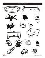
Page 11: ...REV 10 10 12 Page REPLACEMENT PARTS 1 2 3 11 12 13 8 16 7 15 14 ON OFF HI LOW 17 SKYTECH SKYTECH SKYTECH SKYTECH 19 6 5 18 4 ...

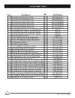
Page 12: ...t shown 1 ST3 100 1030 10 DSI Valve Box Assembly not shown 1 ST2 010 1010 11 Stainless DSI Fire Pit Valve Box Only 1 ST3 100 1020 13 Stainless DSI Fire Pit Valve Box Cover Only 1 ST3 100 1021 13 Control Module AF 5000MOD 1 Inside valve box 1 ST3 030 1039 14 AF 4025 DSI Gas Valve 5 0 WC Natural Gas 1 ST2 080 1025 15 1 2 Flex Gas Line 46 inch Length 1 T 200 9898 46 16 Air Shutter Orifice NG 13 Used ...

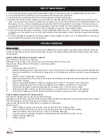
Page 13: ... of Fault Warn users if the pilot is not successfully ignited in 15 seconds How to Clear Press OFF then ON buttons to re attempt ignition What to Check 1 Ensure gas supply is turned on 2 Ensure that the gas line is purged of air Air is common in the gas line if the appliance has just been installed has been disconnected then re connected to the gas line or if the appliance has been unused for an e...

Page 14: ... operating range 8 Make sure that there is not a large metal obstruction between the remote transmitter and the control module Igniter Electrode Sparks Frequently During Operation 1 The control module will generate a spark at the igniter electrode if the system is in the ON position but does not sense a flame 2 Make sure that the flame sensor electrode is clean Soot buildup will insulate the elect...

Page 15: ...ice air mixer for 19 20 pits using 18 inch firestar LP Conversion Kit MODEL FPB 25LPCK Brass orifice air mixer for 25 26 pits 24 inch firestar LP Conversion Kit The following accessories are available from your local firegear dealer distributor Each accessory comes with a separate installation manual Read each instruction thoroughly before installing FCC REQUIREMENTS NOTE THE MANUFACTURER IS NOT R...

Page 16: ...ranty period Travel diagnostic cost service labor to repair the defect and freight charges on warranty parts to and from the factory will be responsibility of the owner Fire Gear LLC will not be responsible for labor charges and or damage incurred in installation repair and replace ment or for incidental or consequential damages This Limited Warranty does not cover any failures or operating diffic...

Reviews: