O
WNER
'
S
PERATION
& M
AINTENANCE
M
ANUAL
ICAF
- Integrated Compressed Air Foam System
FM-0723-0-04 A
Page 1: ...Operation Maintenance Manual FM 0723 0 02 A...
Page 2: ...Integrated Compressed Air Foam System with Electric Release Owner s Operation and Maintenance Manual FM 0723 0 04 A...
Page 3: ...Integrated Compressed Air Foam System FM 0723 0 04 A FireFlex Systems Inc 1935 Lionel Bertrand Blvd Boisbriand QC Canada J7H 1N8 Tel 450 437 3473 Toll free 866 347 3353 Fax 450 437 1930 Web Site http...
Page 4: ...n Preliminary inspection before placing the system in service Placing the system in service Important settings Mechanical trim section 1 System operation Post discharge instructions Inspection tests a...
Page 5: ...ystem 3 Operation 4 Recharge cylinders 5 Maintenance and Inspection Foam Supply Section FM 0723 0 13 1 Foam storage tank 2 Foam concentrate 3 Foam tank design and selection 4 Interconnection piping to...
Page 6: ...l is prohibited While all reasonable efforts have been taken in the preparation of this manual to assure its accuracy FireFlex Systems Inc assumes no liability resulting from any errors or omissions i...
Page 7: ...OWNER S OPERATION MAINTENANCE MANUAL ICAF Integrated Compressed Air Foam System FM 0723 0 04 A...
Page 8: ...g air under pressure water and foam concentrate in the right proportions and then sending it through piping for distribution on the protected area Integrated Compressed Air Foam ICAF Systems for fixed...
Page 9: ...guration required to supply the nozzles in the hazard s Remote Controlled Unit This unit is used when an additional zone is required to be protected by the same system This unit includes all the mecha...
Page 10: ...1 Control Panel energizes the Solenoid Valve R2 open the pneumatic control line is then pressurized causing the water air and foam pneumatically activated control valves A1 B9 F1 to open simultaneous...
Page 11: ...upply must be CLOSED see AIR SUPPLY SECTION Flow Test Valve B6 and main drain valve B16 must be CLOSED Alarm test valve B5 must be CLOSED Emergency Release valve R1 is CLOSED System flushing valve A3...
Page 12: ...line vent Solenoid Valve is closed R4 Electric Release In the SET condition water supply pressure is trapped in the priming chamber by a spring loaded check valve B4 and the normally closed water pneu...
Page 13: ...Prior to proceeding notify all Authorities Having Jurisdiction Consideration should be given to employ a fire patrol in the affected areas ICAF Systems that have been exposed to a fire must be returne...
Page 14: ...en full flow develops from Flow Test Valve B6 close the Flow Test Valve Verify that there is no flow from the System Main Drain Valves B16 11 Close the System Main Drain Valve s B16 12 Fully open and...
Page 15: ...those established in this document 3 These tasks shall be performed by FireFlex s authorized personnel who have developed competence through training and experience 4 It is the responsibility of the...
Page 16: ...dicates that normal pressure is being maintained The flow control valve shall be externally inspected to verify the following 1 The valve is free from physical damage 2 All trim valves are in the appr...
Page 17: ...lapse between operation of detection systems and water delivery time to the protected area shall be recorded for open discharge devices Discharge Patterns The discharge patterns from all of the nozzl...
Page 18: ...ng upon subsequent alarm GROUND FAULT A yellow lamp that illuminates steadily during a ground fault condition PARTIAL DISABLE A yellow lamp that illuminates steadily when any input or output circuit i...
Page 19: ...duly acknowledged a full reset sequence should take only a few seconds to complete Under normal conditions pressing on the SYSTEM RESET key make the local sounder beep once and will also perform a LAM...
Page 20: ...additional details In the TIMER STATUS screen all the set values of the various timers are displayed as shown in the example below actual screen may differ depending on system configuration Pressing o...
Page 21: ...below Note Should the start up routine take more than 2 minutes and system seems to be hung perform a cold reset by removing power to the unit and back If problem continues contact your nearest FireF...
Page 22: ...lays a 5 digit code used by the factory describing module placement circuit type zone number and type of activation Refer to TROUBLESHOOTING in Appendix D for additional details on these codes DATE di...
Page 23: ...off function is provided The CAF discharge can be manually suspended using the following sequence of operation 1 Press and hold the function key F3 labelled System Shut Off on the keypad of the ARC 1...
Page 24: ...ement Detail 12 12 BCA Grounding Bar 12 TBB N U Factory Wired TBB Module 1 2 3 4 6 5 Releasing Panel Control Modules 8 3 7 2 Input Output Modules Blank 1 9 N U 8 7 11 10 Blank Blank 1 2 3 4 PSA Transd...
Page 25: ...rface FACTORY WIRING SOA Module Supervised Output Circuits TYPICAL CLASS B STYLE Z CIRCUITS FACTORY WIRING ARA Module Auxiliary Relay Outputs SIA Module Supervised Input Zones TYPICAL CLASS B STYLE B...
Page 26: ...ushing valve F5 must both be CLOSED All gauges B11 B12 and E3 should show 0 psi pressure Foam concentrate tank T1 must be filled according to the procedure described in the FOAM SUPPLY section Compres...
Page 27: ...Page 2 of 4 ICAF Integrated Compressed Air Foam System System Trim Section FM 0723 0 09 A Trim Schematic System with electric release...
Page 28: ...heck valve B9 Water pneumatically actuated control valve N C B10 Water supply control valve B11 Priming pressure water gauge valve B12 Water supply presure gauge valve B13 Clapper check valve B14 Flow...
Page 29: ...Page 4 of 4 ICAF Integrated Compressed Air Foam System System Trim Section FM 0723 0 09 A...
Page 30: ...o protective caps have to be removed and most importantly no tubing or fittings are required to be installed after receiving The cylinders bank is also provided with a refilling outlet C9 which allows...
Page 31: ...rs must be recharged by FireFlex or its trained authorized agent Contact FireFlex After Sales Support Department for information about the nearest authorized agent to your location 5 Maintenance and i...
Page 32: ...23 0 12 B Figure 2 Compressed Air Cylinders Bank Rack mounted Air supply Components C1 Cylinders rack C2 Compressed air cylinder C3 Safety release disk C4 Cylinder valve C5 Pressure regulator C6 Press...
Page 33: ...Page 4 of 4 ICAF Integrated Compressed Air Foam System Air Supply Section FM 0723 0 12 B This page is left blank intentionally...
Page 34: ...For further details see the Foam Concentrate Data Sheet Environmental and Toxicological Information Foam concentrates used with Compressed Air Foam Systems are biodegradable However as with any subst...
Page 35: ...tube is drained CLOSE tank drain valve T3 both sight gauge isolation valves T4 and the tank refill vent valve T6 b If level is below normal add foam concentrate up to normal level by following FILLIN...
Page 36: ...en from the Storage tank drain valve T3 Foam samples may be sent to FireFlex Systems Either glass or plastic bottles are satisfactory provided they are leak proof and well packaged The sample s must b...
Page 37: ...approximately 1 minute or until pressure stabilizes at the Foam injection line pressure gauge F4 4 CLOSE foam injector flushing valve F5 5 Foam injection line pressure gauge F4 should vent quickly and...
Page 38: ...13 D Figure 2 Foam storage tank schematic Foam storage tank components T1 Foam storage tank T2 Dip tube T3 Storage tank drain valve T4 Level sight gauge isolation valve T5 Foam level sight gauge T6 Fo...
Page 39: ...Page 6 of 6 ICAF Integrated Compressed Air Foam System Foam Supply Section FM 0723 0 13 D This page is left blank intentionally...
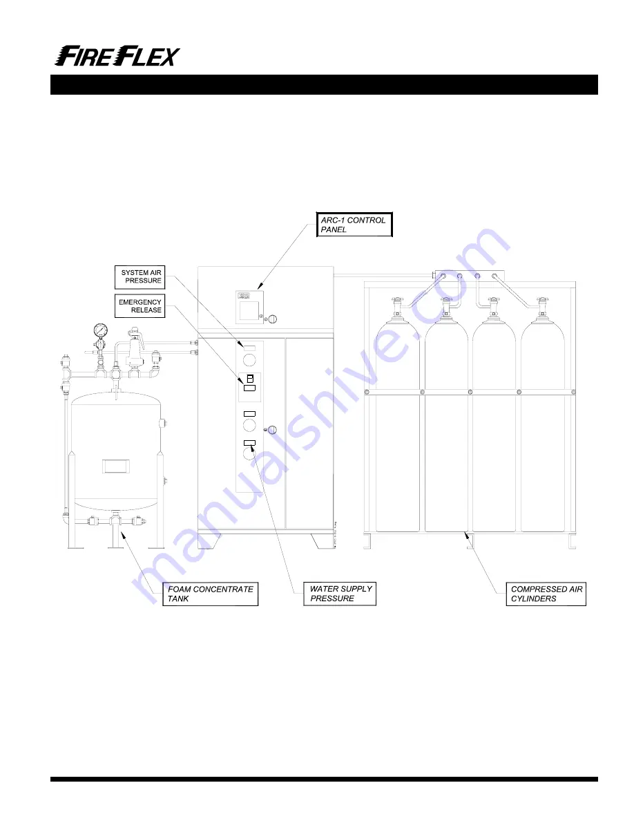
Page 40: ...on system auxiliary contacts and signaling devices Knockouts can be drilled by the installing contractor on site but have to meet the restrictions indicated on Figure 2 Gauges to indicate air water su...
Page 41: ...te to access anchoring holes 2 MAX W SIZE VARIES ACCORDING TO MIXING CHAMBER SIZE SCH 40 GROOVED OUTLET MIXING CHAMBER 1 MIXING CHAMBER 2 SCH 40 GROOVED OUTLET OPTIONAL OUTLET DRILLED ONLY WHEN 2 nd M...
Page 42: ...only to avoid internal components and about 1 2 from cabinet rear edge as shown 5 3 9 15 FM 072C 0 251 B dwg Wiring Routing Wiring shown in Figure 3 below indicates typical Wiring Routing for Power Li...
Page 43: ...Page 4 of 4 ICAF Integrated Compressed Air Foam System System Characteristics Section FM 0723 0 14 C This page is left blank intentionally...
Page 44: ...Page 1 of 2 ICAF Integrated Compressed Air Foam System Notes Warranty FM 0723 0 16 B User Notes...
Page 45: ...ow long an expressed warranty lasts so the above limitations may not apply to you Under no circumstances shall the Manufacturer be liable for any loss of or damage to property direct or indirect incid...