


EQUIPMENT:
FIRE
CLASS
PRECEPT EN13
PUBLICATION:
FIRECLASS PREC EN13 INST
ISSUE No. & DATE:
2 22/07/2021
PAGE 17 of 32
11.7.2 Zones
NOTE: The panel determines the normal
operating current for each zone when the panel
is powered up, allowing 60 seconds for the
attached devices to settle down. If any work is
carried out on a zone circuit after power-up,
then the panel must be powered down and then
powered back up to allow the new zone circuit
current to be checked.
Work logically and systematically through each
zone.
1. Power down the panel.
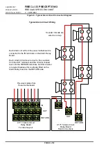
2. Remove the EOL device from the zone terminals
of the first zone. Connect the cables for the zone
to the zone terminals, observing correct polarity.
3. Power up the panel.
After about 60 seconds, if all circuits are
determined to be healthy and no other faults are
present, the panel should be silent with only the
Power Supply On indication illuminated.
If any zones remain in fault after the cable check
has ended, do the following:
a) Power down the panel.
b) Disconnect the cables from the faulty zone
and repeat the cable resistance
measurements described previously.
c) Check that all detectors and MCPs are
correctly wired.
d) Check that the number of devices fitted
does not exceed the maximum permitted.
e) Check that the correct EOL device is fitted.
f) After all checks have been carried out, re-
connect the cables to the zone terminals
and repeat the power-up process.
4. Repeat steps 1 to 3 for each remaining used
zone circuit.
5. Zone fault conditions:
o
Check the fault monitoring of the cable is
correct by disconnecting the end-of-line device
on the zone. Check that the fault condition is
indicated on the correct zone on the fire panel.
o
Reconnect the EOL device and check that the
fault indication clears.
o
Apply a short circuit across the EOL device
and check that the panel gives the correct fault
indication.
o
Remove the short circuit and check that the
fault indication clears.
6. Zone fire conditions
o
Starting with the device nearest the panel,
operate each manual call point and detection
device on the zone in turn.
o
After operation of each device confirm:
•
The fire indication is provided on the panel
on the correct zone.
•
The fire alarm devices operate correctly in
line with the panel configuration.
•
The Fire Routing and Fire protection outputs
operate correctly in line with the panel
configuration.
o
Press the Silence Alarms and the Reset
buttons after each device test and check the
alarm clears (Manual Call Points must be
manually reset before resetting the panel).
7. Detector removal operation.
o
Remove the 1st detector along the zone cable
[counting from the panel] on the zone and
check that the correct zone fault is indicated on
the panel.
o
For non I.S. zone applications:
•
Operate a manual call point between the
detector that has been removed and the EOL
capacitor. Check that the panel reacts as
described above for a fire condition.
•
Refit the detector, reset the manual call point,
press the “Silence Alarms” button and then
the “System Reset” button on the panel’s
display board and check that the control
panel returns to its normal state.
•
Repeat for all detectors on the zone.
o
For I.S. zone applications:
•
Operate a manual call point ensuring that the
correct fire alarm condition is raised on the
panel (assuming the installation complies
with BS5839).
•
Continue to check the operation of all other
manual call points on the zone, resetting the
manual call point and silencing/resetting the
panel at each stage.
•
Refit the detector and check that the control
panel returns to its normal state.
•
Continue to test each of the other detectors
in turn, checking for correct fault indication in
each case.
8. Repeat steps 5 to 7, one zone at a time, until all
the zones are commissioned.
9. Any faults that are found must be traced and
rectified before proceeding.
11.7.3 Class Change Input
1. Connect the Class Change switch to the class
change input on the motherboard.
2. Operate the class change switch and observe:
i) The alarms sound for 5 seconds then stop.
ii) The internal buzzer on the panel
does not
operate.
iii) The internal buzzer on repeaters
does not
operate.
3. De-activate the class change switch


