

Contact us for assistance: (866) 985-7877 | www.wtliving.com
10
OPERATING INSTRUCTIONS
CAUTION
Do not attempt to operate until you have read
and understand all General Safety Information
in this manual and all assembly is complete
and leak test has been performed.
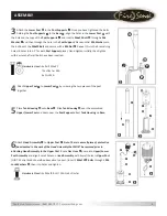
BEFORE TURNING GAS SUPPLY ON:
1. Your heater was designed and approved
for OUTDOOR use only. Do NOT use it
inside a building, garage, or any other enclosed area.
2. Make sure surrounding areas are free of combustible materials, gasoline, and other
flammable vapors or liquids.
3. Ensure that there is no obstruction to air ventilation. Be sure all gas connections are
tight and there are no leaks.
4. Be sure the cylinder cover is clear of debris. Be sure any component removed during
assembly or servicing is replaced and fastened prior to starting.
BEFORE LIGHTING:
1. Heater should be thoroughly inspected before each use, and by a qualified service
person at least annually. If re-lighting a hot heater, always wait at least 5 minutes.
2. Inspect the hose assembly for evidence of excessive abrasion, cuts, or wear. Suspected
areas should be leak tested. If the hose leaks, it must be replaced prior to operation.
Only use the replacement hose assembly specified by the manufacturer.
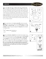
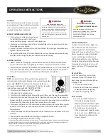
LIGHTING:
NOTE: For initial start or after any cylinder change, hold the
control knob in for 2 minutes to purge air from all gas lines before
proceeding.
NOTE: This heater has an Electronic Ignition and
will require installation of 1 – AAA battery. The battery should be
installed by unscrewing the RED IGNITER BUTTON.
1. Turn the control knob to the “OFF” position.
2. Fully open the LP cylinder valve.
3. Turn the control knob half way between the small flame and the large flame symbols.
4. Push control knob in and then push the RED igniter button to ignite the main burner.
Repeat until the burner ignites. Keep the control knob fully pushed in for an additional
30 seconds after the burner ignites, then release the control knob.
5. To increase the flame, turn the control knob clockwise toward the large flame symbol.
To decrease the flame, turn the control knob counter clockwise towards the small
flame symbol.
6. To turn the appliance OFF, push down the control knob and turn clockwise to the OFF
position.
7. Wait at least 5 minutes before attempting to re-light the heater.
8. Turn the gas cylinder valve to OFF or closed.
If you experience any ignition problems, please consult “Troubleshooting” page. Caution: Avoid inhaling fumes
emitted from the heater’s first use. Smoke and odor from the burning of oils used in the manufacturing will
appear. Both smoke and odor will dissipate after approximately 30 minutes.
The heater should NOT produce thick black smoke.
WARNING
Very hot while in operation!
Never lean over the heater while in use. Do
not touch the Burner Assembly while the
heater is in operation. Wait until the heater
has cooled down after use before moving
or touching any surfaces. Failure to comply
with these instructions may result in serious
bodily injury.
DANGER!
FOR OUTDOOR USE ONLY
CARBON MONOXIDE HAZARD
Never use this inside a house, or other
unventilated or enclosed areas. This heater
consumes air (oxygen). Do not use in
unventilated or enclosed areas to avoid
endangering your life.
WHEN HEATER IS ON:
Emitter screen will become bright red
due to intense heat. The color is more
visible at night. Burner will display
tongues of blue and yellow flame. These
flames should not produce thick black
smoke, indicating an obstruction of
airflow through the burners. The flame
should be blue with straight yellow tops.
If excessive flame is detected, turn off
heater and consult “Troubleshooting”
page.
RE-LIGHTING:
Note: For your safety, control knob
cannot be turned OFF without first
depressing the control knob and then
rotating to OFF.
1. Turn control knob to OFF.
2. Wait at least 5 minutes to allow gas
to dissipate before re-lighting.
3. Repeat the “Lighting” steps.
SHUT DOWN:
1. Turn control knob clockwise to
OFF while depressing the knob.
(Normally, burner will make a slight
popping noise when extinguished).
2. Turn cylinder valve clockwise to
OFF and disconnect regulator when
heater is not in use. NOTE: After use,
some discoloration of the emitter
screen is normal.


