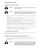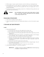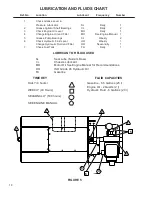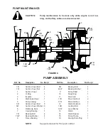
D. INSTALLING NEW SEAL ASSEMBLY (#4)
(DO NOT UNWRAP THE NEW SEAL ASSEMBLY UNTIL YOU ARE READY TO INSTALL. ALL
PARTS OF THE ASSEMBLY ARE PACKED IN SEQUENCE OF INSTALLATION.)
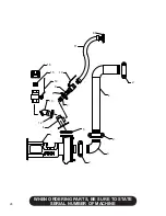
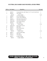
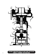
1. To replace the seal assembly (4), perform the above operations under cleaning and remove pump
casing (5) by removing the four bolts (7B) holding the casing and the casing bearing (7) to the pump
frame (15).
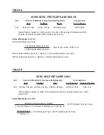
2. After cleaning all parts including pump shaft, begin the reassembly of the pump. Install grease
retainer seal (6) with the cavity portion of the seal facing inward. Rebolt the casing and the casing
bearing (7) onto the clutch housing using the four cap screws (7B). Using a light oil lubricant (3 in
1), install the ceramic seat with its neoprene holder into the seal recess making sure it is square with
the shaft. Lubricate the inside of the bellows assembly with a light oil and check to be sure the steel
ring is stuck (glued) to the end of the assembly. Slide the bellows assembly onto the shaft and push
till the steel ring is against the ceramic seat.
3. Install the seal spring on the hub of the impeller. After coating the threads on the pump shaft with
an anti-seize compound, install the impeller - seating it securely.
4. Utilizing the rubber O-Ring gasket (2) reinstall suction cover using the eight cover bolts (5B). At
this time, check to see that the pump runs freely. If the impeller rubs the cover plate, either the
impeller is not tight on the shaft or the cover plate needs readjustment - see “impeller clearance”.
Tighten these bolts uniformly using 15 ft. pounds (165 kg/m) on the torque wrench.
5. After reinstalling the suction pipe assembly, lubricate and tighten the victaulic clamps. Service the
automatic lubricator.
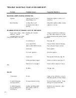
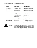
TROUBLE SHOOTING YOUR HYDROSEEDER®:
Because of the tremendous work load usually placed upon the HydroSeeder®, minor malfunctions will
occur from time to time. If not remedied immediately, they could lead to poor performance and damage to
the equipment. This section describes possible problems and the action to correct them.
1. Foam in the tank and air entrainment.
The mixture of dry materials with water will sometimes cause excessive foaming while others will
cause air entrainment. This is exhibited by erratic discharge and/or a drop in pressure and distance.
Some solutions are:
A. As the slurry level drops in the tank, slow the agitator.
B. Add 2 or 3 ounces (4 to 6 cl) of an antifoaming agent to the tank.
C. If you can determine which additive is causing the air problem, either add it last or not at all
- unless it’s the water.
D. Reduce recirculation time as much as possible.
2. Plugging or clogging:
DANGER:
Turn off engine and disconnect battery cables before working
on equipment. Serious injury or death can result from moving
parts or high pressure spray.

