


17
16
4 . Turn on power to the circuit and read the display.
5 . Aft er measuring current, t urn off power to the circuit and discharge all high-
voltage capacit ors. Dis connect t he meter and rest ore the circuit t o normal
o p e r a t i o n .
Tips for measur ing current
When measuring a 3-phase system, special attention should be taken t o the
phase to phase volt age which is significantly higher than t he phase to eart h
volt age. To avoid exceeding the voltage rat ing of t he prot ecti on f us e(s)
accidentally, always consider the phase to phase volt age as the working voltage
for the prot ection fuse(s).
When measuring current , t he meter’s internal shunt resistors develop a voltage
across the meter’s t erminals called “burden voltage”.
This voltage drop may affect precision circuits or measurements.
Current ( , , ) Measurements
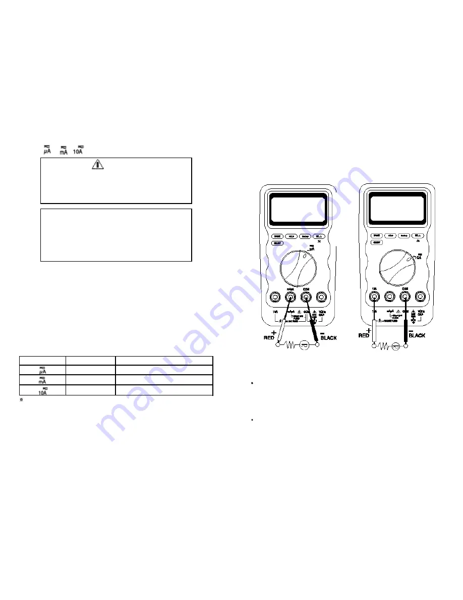
Current is the flow of electrons through a conductor. To measure current, you must
open the circuit under test, then place the meter in series with the circuit.
The available current ranges are :
400.0 µA, 4000 µA, 40. 00 mA, 400.0 mA, 4.000 A, and 10.00 A
The meter def aults at d c. Press S E L E C T button momentarily to select a c .
To measure dc or ac current,
1 . Turn off power to the circuit and discharge all high-voltage capacitors.
2 . Insert the black lead int o t he C O M terminal and the red lead into an input
terminal appropriate for the measurement range as the following table.
To avoid blowing the meter’s 440 mA fuse, use the mAµA terminal only if you are sure the
current is less t han 400 mA.
3 . Open the current path to be t ested. Touch t he red probe to the more positive
side of the break and touch the black probe to the more negative side of the
break. (Reversing the leads will produce a negative reading, but will not damage
the met er.)
Warning
Never attempt an in-circuit current measurement where the
open-circuit potential to earth is greater than 1000V. You may
damage the meter or be injured if the fuse blows during such
a measurement.
Caution
Check the met er fuses before measuring current. Use the
proper t erminals , f unct i on, and range f or c urrent
measurements. Never place the probes in parallel with any
circuit or component when the test leads are plugged into the
current terminals.
Range
Ranges
Input
mAµA
mAµA
10A
400.0 µA, 4000 µA
40.00 mA, 400.0 mA
4.000 A, 10.00 A
SERIES CONNECTION
S ERIE S CONNECTION