

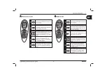
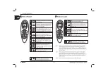


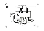
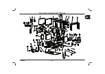


HB9000
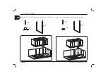
(system 1)
(system 2)
(system 3)
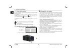
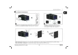
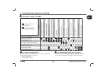
FLOOR CUTS MAP
5 1 . 8
3
1
.9
7
1
.8
16
5 5
D R A I N H O L E
FI XIN G H OL E
(s y st em 1 )
FI XIN G H OL E
(s y st em 1 )
FI X IN G H OL E
(s yst em 1 )
FI X IN G H OL E
(s yst em 1 )
F
RO
NT
F I XI N G H O LE
(s ys te m 2 )
F I XI N G H O L E
( sys te m 2 )
F I XI N G H O LE
(s ys te m 2 )
F IX I NG H OLE
(s ys te m 2 )
F
I
X
I
N
G
H
O
L
E
(
s
y
s
t
em
3)
F
I
X
I
N
G
H
O
L
E
(
s
y
s
t
em
3)
F
I
X
I
N
G
H
OL
E
(
s
y
s
t
em
3)
F
I
X
IN
G
H
O
LE
(
s
y
s
t
em
3)
I N L E T
2
.
8
6
1 9 1
2
1 3 5 . 4
1
84
.4
O U T L E T
HB9000
734
3
9
8
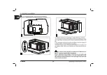
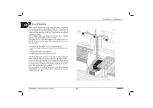
KEEP THIS DISTANCE BETWEEN THE UNIT AND THE SURROUNDING WALLS
1 0 6
70 . 5
2
1
6
4
6
3
0
30
2 00
3
0
TO THE SIDE OF THE EXTERIOR WALL
1
2
3
4
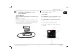
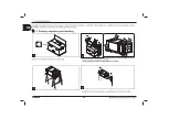
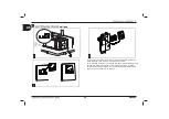
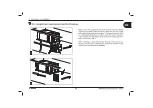
Hole as an option
(to optimize the performance of the unit)
Installation:
1.Open the side cover EPP,and have the
foam sticked around the air outlet.
2.Make a whole of the indicated size in
proper position.
3.Fix the grille.
4.Have the unit installed.
(Pls check when installation foam
thickness decided)
Summary of Contents for HB 9000
Page 1: ...9...
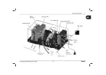
Page 4: ...HB9000 2 brand certificate mode technical specifications manufacturer information fan blower C...
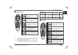
Page 5: ...HB9000 3 Wall pad E Fan blower C...
Page 6: ...HB9000 wall pad...
Page 7: ...HB9000...
Page 8: ...HB9000...
Page 9: ...HB9000...
Page 10: ...HB9000...
Page 13: ...HB9000...
Page 14: ...12 HB9000...
Page 15: ...HB9000...
Page 18: ...HB9000 the a c fixing...
Page 21: ...HB9000 2 300cm 220V 60Hz...
Page 22: ...HB9000 2 300cm...
Page 23: ...HB9000...
Page 25: ...HB9000 9000...


