


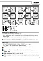


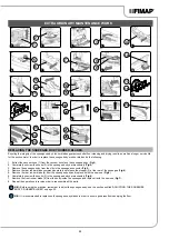


ACTIVATING THE SIDE BRUSH
If the side brush needs to be used during the floor scrubbing operations (and therefore with the brush head in its working position), press the
side brush head activation/deactivation button (11) on the left-hand side of the steering column (
Fig.14
).
N.B.:
When the side brush is in function, the LED indicator light inside the button (11) will be on.
N.B.:
By pressing the button (11), the side brush head will begin to move towards the outside of the machine, and the solenoid valve will
only begin to dispense the detergent solution once it has reached its working position (valid only for scrubbing versions).
By pressing the button (11) the side brushes will start to move towards the floor and the gear motors of the side brushes will start to work
(valid only for sweeping versions).
N.B.:
In order to bring the side brush head back to its resting position, press the button (11) (valid only for scrubbing versions).
In order to bring the side brushes back to their resting positions, press the button (11) (valid only for sweeping versions).
N.B.:
If the central brush head is raised with the side brush head in its working position, the lever (4) on the steering column (
Fig.15
) can
be turned in order to bring the side brush head back to the rest position. The LED indicator inside the button (11) will nevertheless remain
on to indicate that if the central brush head is brought back to its working position, the side one will move to the right (valid only for
scrubbing versions).
If the central brush head is raised with the side brush head in its working position, by turning the lever (4) on the steering column (
Fig.15
) the
side brushes can also be brought into the rest position. The LED indicator inside the button (11) will nevertheless remain on to indicate that
if the central brush head is brought back to its working position, also the side brushes will be brought into contact with the floor (valid only for
scrubbing versions).
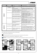
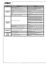
NUMBER
TYPE
DESCRIPTION
AL_60
Function
Time-out Actuator 1
AL_61
Function
Amperometric Actuator 1
AL_62
Function
Overcurrent Actuator 1
AL_63
Function
Incorrect limit switches - actuator 1
AL_64
Function
Time-out Actuator 2
AL_65
Function
Amperometric Actuator 2
AL_66
Function
Overcurrent Actuator 2
AL_67
Function
Incorrect limit switches - actuator 2
AL_68
Function
Time-out Actuator 3
AL_69
Function
Amperometric Actuator 3
AL_70
Traction
Overcurrent Actuator 3
AL_71
Traction
Incorrect limit switches - actuator 3
NUMBER
TYPE
DESCRIPTION
AL_80
Traction
Overtemperature
AL_81
Traction
Power board damaged
AL_82
Traction
Main fuse faulty
AL_83
Traction
Main contactor faulty
AL_84
Traction
Main contactor faulty - CC
AL_85
Traction
Overcurrent - traction output
AL_86
Traction
Amperometric - traction output
AL_87
Traction
Motor reading
AL_88
Traction
Electric brake fault
AL_89
Traction
Pedal fault
AL_90
Traction
Pedal pressed
AL_91
Traction
Encoder fault
ACTIVATING DETERGENT SOLUTION RECYCLING (FLR VERSION)
Upon request the machine can be fitted with a system that allows the detergent solution to be recycled so that productivity can be increased,
since the number of stops needed to empty and fill the tanks is reduced. As a result less water and detergent are used, thereby making the
operator safer, who comes into contact with the chemical products less frequently, and the operation is more environmentally friendly. If the
machine being used features the system for recycling the detergent solution, once the machine has been started up, press the FLR system
activation - deactivation button (12), on the left side of the steering column (
Fig.16
). Once the work operations have been completed, remember
to shut off the FLR system by pressing the button (12).
N.B.:
When the FLR system is in function, the LED indicator light inside the button (12) will be on.
N.B.:
At the end of the working day, perform all the procedures listed in the section “ROUTINE MAINTENANCE” on page 26.
TAG INSERTION (FFM VERSION)
To activate the automatic fleet management data recording function, which is valid for machine versions with the FFM system, after the screen
displaying the machine programming characteristics appears, insert the TAG in the slot (13) on the right-hand side of the steering column
(
Fig.17
).
N.B.:
If the owner of the TAG just inserted is not enabled to use it, the AL_11 alarm will appear on the control display.
OVERFLOW DEVICE
The machine is not equipped with an overflow device, because the volume of the recovery tank is greater than the capacity of the solution
tank. In extraordinary cases, there is a mechanical device (float) under the recovery tank lid that, when the recovery tank is full, shuts off the
air to the vacuum motor intake to protect it; the sound of the suction motor will then be deeper. Empty the recovery tank (read “DRAINING THE
25