3.
Use
3.1
Commissioning
- Put the controller into operation only if the installation and the
electrical connection have been done correctly.
3.2
Normal operation
- Use the controller in its intended application only.
- Comply with the specifications
- If the controller is damaged, disconnect it immediately.
- It is forbidden to make changes to the device. This violates the
Normative.
3.3
Inexpert handling
- Ignoring the Safety instructions and the Operating instructions.
- Not intended use.
- Making changes or handling the float switch.
- Violation against applicable Law and Standards.
- Using of non original parts.
4.
Maintenance, servicing and spare parts
4.1
Maintenance
- If used correctly, no specific maintenance is required.
4.2
Servicing
- Check and review the state of the housing, the probes and the
correct commutation of the electrical contact, as well.
4.3
Spare parts
- There are no spare parts for these controllers.
5.
Storage
- Store the controller in a dry and dust-free environment.
6.
Disposal
-
- The controller can be recycled.
- The disposal applies to the valid environmental Guidelines
according to the location of the carrier and the local
manufacturing conditions.
on the data plate and the technical
data of this manual.
Switch off the power supply, before disconnecting the device.
2.
Installation
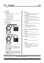
2.1 Preparing for use
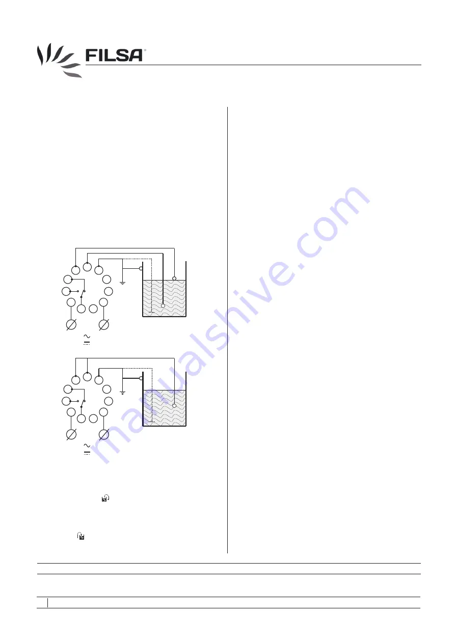
Function in emptying
Function in filling
-
- Verify if you have got all the parts:
•
Conductive control level relay.
•
Conductive probes, if required.
•
Undecal socket, if required.
It is simple: the device has to be installed in a DIN rail using the
undecal socket.
Read the Safety Instructions and the Operating Instructions
before using the controller.
2.2
Mechanical connection
2.3
Electrical connection
Connection diagram
Example: control of a signal level
The relay operates when the liquid reaches the maximum level
electrode (5), and it releases when the liquid goes below the
minimum level (6). For the DC models the selector must be in the
emptying position ( ).
For the AC models, the relay’s output connections must be
modified .For the DC models, the selector must be in the filling
position ( ). The relay operates when the liquid level is below the
minimum electrode (6), and it releases when the liquid level is
above the maximum electrode (5).
L-ED
04
Talleres Filsa, S.A.U.
www.filsa.es
•
•
•
•
•
E-08100 Mollet del Vallès (Barcelona)
Tel.
+34 93 570 46 01
Fax
+34 93 570 24 71 [email protected]
05/14 © by FILSA
MI-LED-EN-04
1
2
3
4
5
6
7
8
9
10
11
L
N
+
-
1
2
3
4
5
6
7
8
9
10
11
L
N
+
-
LED-001
LED-002
FILSA constantly strives to improve its products and reserves the right to modify designs, materials and data without prior notice.
Keep this manual for further questions!

