background image

FS-8700-40 SBT FSI Driver Manual   


Page 16 of 34 

FieldServer Technologies

 1991 Tarob Court Milpitas, California 95035 USA   

Web

: www.fieldserver.com 

Tel

: (408) 262 2299   

Fax

: (408) 262 2269   

Toll Free

: (888) 509 1970   

email

: [email protected] 

5.3.5


Map Descriptor example 2 – Monitoring Analog Loop Devices 

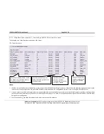
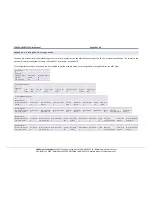
Analog devices on a loop can be monitored for detector voltage, sensitivity voltage and threshold voltage using three analog Map Descriptors: 

//    Client Side Map Descriptors 


Map_Descriptors 


Map_Descriptor_Name  , Data_Array_Name  , Data_Array_Offset  , Function  , Node_Name  , Block_Number  , Length  , Msg_Type 

, Analog_Device  , Scan_Interval 

CD_Analog_Volts1 

, Analog_Volts 

, 0 

, Rdbc 

, Panel1 

, 1 

, 60 

, Analog_Volts 

, 0 

, 300s 

CD_Analog_Sens1  

, Analog_Sense 

, 0 

, Rdbc 

, Panel1 

, 1 

, 60 

, Analog_Sense  , 0 

, 300s 

CD_Analog_Thres1 

, Analog_Thres 

, 0 

, Rdbc 

, Panel1 

, 1 

, 60 

, Analog_Thres  , 0 

, 300s 


Note: If necessary, use more analog Map Descriptors with other Analog_Device numbers to poll other devices on the loop. 

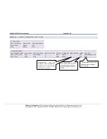
Scan Interval on analog 
pollers may not be shorter 
than 300s to prevent 
flooding the Foreign 
Systems Interface.  

Use Float Data Arrays for 
the analog Map 
Descriptors to get the 
full analog value. 

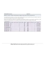
0 : devices 1-60 
1 : devices 61-121 
2 : devices 122-182 
3 : devices 183-243 
4 : devices 244-252 

Summary of Contents for FS-8700-40

Page 1: ...Sierra Monitor Company APPLICABILITY EFFECTIVITY Effective for all systems manufactured after October 2011 Driver Manual Supplement to the FieldServer Instruction Manual FS 8700 40 SBT FSI Siemens Building Technologies Foreign Systems Interface ...

Page 2: ...ring a MXL XLS Device for Events 14 5 3 5 Map Descriptor example 2 Monitoring Analog Loop Devices 16 6 Configuring the FieldServer as a SBT FSI Server 17 6 1 Server Side Connection Descriptors 18 6 2 Server Side Node Descriptors 19 6 3 Server Side Map Descriptors 19 6 3 1 FieldServer Specific Map Descriptor Parameters 19 6 3 2 Driver Specific Map Descriptor Parameters 20 6 3 3 Map Descriptor examp...

Page 3: ...for this driver FieldServer Technologies PART Description FS 8917 03 RJ45 to DB9F connector adapter FS 8917 16 Pigtail cable for RJ45 Port for RS 232 use 2 2 Provided by the Supplier of 3rd Party Equipment 2 2 1 Hardware Part Description Siemens MXL XLS System Siemens NIM 1R Network Interface Module for MXL usage Siemens RPM Network Interface Module for XLS usage 500 699103 Siemens NIM 1W Network ...

Page 4: ...itches in SW2 to open or OFF See connection diagram below Connect the NIM 1R to an RS 232 port on the Fieldserver as depicted in the fiagram below brown circle Connect the NIM W to an RS 485 port on the FieldServer as depeicted in the diagram below FieldServer P1 1 8 2 3 4 1 6 7 8 5 10 11 12 9 14 15 16 13 TB4 Gnd _ Gnd FG _ RS 485 Opto Isolated FS 8917 03 RJ45 to DB9M Connector RJ45 CAT 5 Cable FS...

Page 5: ...ourt Milpitas California 95035 USA Web www fieldserver com Tel 408 262 2299 Fax 408 262 2269 Toll Free 888 509 1970 email support fieldserver com Pinouts FS Function RJ45 Pin DB9F Pin Cerberus Cable Pin Color RX 1 2 14 Red GND 4 5 16 Black TX 8 3 13 Green RTS 7 12 Brown CTS 8 15 White ...

Page 6: ... or Port 3 on the XLS Panel as described in the connection drawing Pins 6 and 7 on the Port 2 Connector must be jumpered to enable RS 232 Port 3 FieldServer P1 1 8 2 3 4 1 6 7 8 5 10 9 RXD TXD RTS Do not use CTS Do not use GND RXD TXD RTS Do not use CTS Do not use GND Port 1 RS 232 Port 3 RS 232 2 3 4 1 6 7 5 Port 2 RS 485 RS 232 Port FieldServer Part 8917 16 Pigtail for RJ45 Port Connect to one o...

Page 7: ...need to be configured for MXL XLS in the configuration file The driver does not support MXL and XLS panels networked together One FSI panel may be connected per FieldServer port but multiple panels may be connected per FSI The following diagram illustrates two possible connection configurations Configuration 1 One FSI Panel per FieldServer per port one Panel per FSI FSI FSI Panel Panel Configurati...

Page 8: ...ate correct storage of the relevant data Section Title Data_Arrays Column Title Function Legal Values Data_Array_Name Provide name for Data Array Up to 15 alphanumeric characters Data_Array_Format Provide data format Each Data Array can only take on one format 5 Int16 Uint16 Bit Data_Array_Length Number of Data Objects Must be larger than the data storage area required by the Map Descriptors for t...

Page 9: ... specified for the poller Map Descriptor Counter offsets into the Data Array per event type are indicated below Event Counter Offset Fire Alarm In 0 Fire Alarm Out 1 Fire Alarm Acknowledge 2 Trouble In 3 Trouble Out 4 Trouble Acknowledge 5 Supervisory In 6 Supervisory Out 7 Supervisory Acknowledge 8 Security Alarm In 9 Event Counter Offset Security Alarm Out 10 Security Alarm Acknowledge 11 Status...

Page 10: ...ond 3 In addition to the two sets of event counters alarm bit arrays are set up for 8 modules 1 to 8 per device If the required configuration falls within this size only the Server side of the FieldServer needs to be configured To connect to a device using Modbus RTU protocol configure the interface as if the FieldServer were another Modbus PLC and create a Map Descriptor to assign a Modbus addres...

Page 11: ...col Specify protocol used Cerberus SBT FSI Enhanced_Protocol Enables legacy or enhanced protocol MXL panels do not currently support Enhanced_Protocol so this parameter must be set to No for MXL The parameter is normally set to Yes for XLS but may be set to No if problems are being experienced Yes XLS No MXL System_Type Specifies Siemens Panel type MXL XLS Block_Acks 7 Specifies if the driver uses...

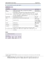
Page 12: ...es Node_Name Node_ID Protocol Port Panel1 1 SBT FSI P1 5 3 Client Side Map Descriptor Parameters 5 3 1 FieldServer Related Map Descriptor Parameters Column Title Function Legal Values Map_Descriptor_Name Name of this Map Descriptor Up to 32 alphanumeric characters Data_Array_Name Name of Data Array where data is to be stored in the FieldServer One of the Data Array names from Section 4 Data_Array_...

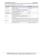
Page 13: ...he Data Array used on the Map Descriptor is not of a bit type Poller Fire_Alarm Fire_Ack Trouble Trouble_Ack Super Super_Ack Secur Secur_Ack Status Test Audible Reset Analog_Volts Analog_Sense Analog_Thres Entity_Arm_Disarm 8 Entity_Activate_Deact 9 Analog_Device Indicates range of device data to be requested by analogs 0 devices 1 60 1 devices 61 121 2 devices 122 182 3 devices 183 243 4 devices ...

Page 14: ... resides Client Side Map Descriptors Map_Descriptors Map_Descriptor_Name Data_Array_Name Data_Array_Offset Function Node_Name Block_Number Length Msg_Type CD_Poller1 Event_Counts1 0 RDBC Panel1 1 19 Poller CD Client Descriptor Specifies lowest panel number from which events will be received Refer to Appendix A 2for more information Specify length in multiples of 19 events according to Block Number...

Page 15: ...ap Descriptors may be defined for particular events to be monitored as per the Msg_Type Should events happen for which no Map Descriptors are defined error messages will occur on the FieldServer It may therefore be useful to add dummy Map Descriptors especially for ack responses to prevent nuisance error messages 2 Passive Map Descriptors with Node_Name the same as the poller Map Descriptor will o...

Page 16: ...ray_Name Data_Array_Offset Function Node_Name Block_Number Length Msg_Type Analog_Device Scan_Interval CD_Analog_Volts1 Analog_Volts 0 Rdbc Panel1 1 60 Analog_Volts 0 300s CD_Analog_Sens1 Analog_Sense 0 Rdbc Panel1 1 60 Analog_Sense 0 300s CD_Analog_Thres1 Analog_Thres 0 Rdbc Panel1 1 60 Analog_Thres 0 300s Note If necessary use more analog Map Descriptors with other Analog_Device numbers to poll ...

Page 17: ...ould poll the emulation driver on the FieldServer to get the same data as from a conventional MXL XLS Server Up to 99 panels can be emulated with the driver A Map Descriptor has to be defined for each type of remote device that would normally exist in a MXL XLS Server The following types can be used Device Type Fire Alarm In Fire Alarm Out Fire Alarm Acknowledge Trouble In Trouble Out Trouble Ackn...

Page 18: ...mally set to Yes for XLS but may be set to No if problems are being experienced Yes XLS No MXL System_Type Specifies Siemens Panel type MXL XLS Echo Specifies if the server should echo the client s polls Yes No Baud Specify baud rate 110 115200 standard baud rates only 19200 Parity Specify parity Even Odd None Mark Space Data_Bits Specify data bits 7 8 Stop_Bits Specify stop bits 1 Vendor limitati...

Page 19: ...if necessary 1 0s Example Server Side Nodes Nodes Node_Name Node_ID Protocol 11 Panel1 1 SBT FSI 6 3 Server Side Map Descriptors 6 3 1 FieldServer Specific Map Descriptor Parameters Column Title Function Legal Values Map_Descriptor_Name Name of this Map Descriptor Up to 32 alphanumeric characters Data_Array_Name Name of Data Array where point data is to be fetched from One of the Data Array names ...

Page 20: ...r as opposed to a starting module number as in the Client Map Descriptor 1 256 Sub_Module Sub module in XLS system 0 99 Component_Address Component address in XLS system 0 99 Length Length of Map Descriptor Specifies number of points for the indicated module Note that MXL systems typically has only 256 points per module 1 256 Msg_Type If this is configured the driver will store a value that indica...

Page 21: ...1 1 256 Secur_Ack SD_Status1 Status 0 Server Panel1 1 256 Status SD_Audible1 Audible 0 Server Panel1 1 Audible SD_Reset1 Reset 0 Server Panel1 1 Reset Notes 1 MXL XLS Server Map Descriptor fields differ in many respects from MXL XLS Client Map Descriptors Please follow the examples clearly and read all notes to ensure a working configuration No poller Map Descriptors may be defined in a configurat...

Page 22: ...S device with analogs The following list of Map Descriptors emulate a MXL Server Server Side Map Descriptors Map Descriptor Map_Descriptor_Name Data_Array_Name Data_Array_Offset Function Node_Name Block_Number Length Msg_Type SD_Analog_Volts1 Volts 0 Server Panel1 1 252 Analog_Volts SD_Analog_Sense1 Sense 0 Server Panel1 1 252 Analog_Sense SD_Analog_Thres1 Thres 0 Server Panel1 1 252 Analog_Thres ...

Page 23: ...ch events will be received The poller Map Descriptor s length has to be at least 19 and has to incremented by 19 for every extra panel above the Block_Number from which events will be received If a poller Map Descriptor length is set below 19 and for example event System Reset is received which needs to be mapped at offset 18 in the Data Array the following kernel message will be printed Cannot st...

Page 24: ...magnetic sources that can generate noise Reason 4 Unrecognized message failure Replace hardware Appendix A 3 Obtaining Point Addresses from the panel report In order to configure the FieldServer to capture data from the Panel the point addresses being used in the panel need to be identified The Panel report that can be printed out from the panel can be used for this purpose but matching the Report...

Page 25: ...o Cerberus MXL Map_Descriptors Map_Descriptor_Name Scan_Interval Data_Array_Name Data_Array_Offset Function Node_Name Block_Number Block_Offset Length Msg_Type POLLER_1 2 0s Counts_1 0 Rdbc Panel1 1 0 19 Poller this is for activation and deactivation of pseudo points PNL_1_Act_Entity 0s Act_Ent 0 Awt Panel1 1 1 10 Entity_Activate_Deact The configuration example in Section 4 can be modified as per ...

Page 26: ...Protocol System_Type P1 19200 Even 7 0 001 0 001 No Cerberus MXL Client Side Map Descriptors Map_Descriptors Map_Descriptor_Name Scan_Interval Data_Array_Name Data_Array_Offset Function Node_Name Block_Number Length Msg_Type POLLER_1 2 0s Counts_1 0 Rdbc Panel1 1 19 Poller Map_Descriptors Map_Descriptor_Name Scan_Interval Data_Array_Name Data_Array_Offset Function Node_Name Block_Number Block_Offs...

Page 27: ...ame Data_Array_Offset Function Node_Name Block_Number Sub_Module Component_Address Block_Offset Length Msg_Type Entity_Types PNL_1_Arm_Disarm 0s Arm_Disarm_Ent 0 Awt Panel1 1 1 1 1 10 Entity_Arm_Disarm Inputs Map_Descriptors Map_Descriptor_Name Scan_Interval Data_Array_Name Data_Array_Offset Function Node_Name Block_Number Sub_Module Component_Address Block_Offset Length Msg_Type Entity_Types Enti...

Page 28: ...unction Node_Name Block_Number Length Msg_Type PNL_1_ASD 300s Current_ASD 0 Rdbc Panel1 1 60 Current_ASD PNL_1_Sens 300s Current_Sens 0 Rdbc Panel1 2 60 Current_Sensitivity The values stored are as follows Current_ASD Current_Sensitivity 0 does not apply does not apply 1 disabled 2 45 foot 2 office 2 59 foot 3 warehouse 2 72 foot 4 lobby 2 86 foot 5 computer room 3 00 foot 6 dormitory 3 13 foot 7 ...

Page 29: ..._Used Uint16 253 Dirty Uint16 253 Map_Descriptors Map_Descriptor_Name Scan_Interval Data_Array_Name Data_Array_Offset Function Node_Name Block_Number Length Msg_Type PNL_1_Comp_Used 300s Comp_Used 0 Rdbc Panel1 1 253 Compensation_Used PNL_1_Dirty 300s Dirty 0 Rdbc Panel1 2 253 Dirty Data values will be stored for device addresses from 0 to Length which can be from 1 to 253 Block_Number sets the mo...

Page 30: ... if any to be stored to so these Request List Map Descriptors cannot be defined simply on their own The Request List Map Descriptors are optional and may be defined per type as needed Map_Descriptors Map_Descriptor_Name Scan_Interval Data_Array_Name Data_Array_Offset Function Node_Name Block_Number Length Msg_Type PNL_1_Req_List_ALR 2 0s 0 ARS Panel1 1 req_list_alarm PNL_1_Req_List_TRB 2 0s 0 ARS ...

Page 31: ...r Block Loop Device Appendix B 3 Using Trouble Codes In order to see the trouble codes for incoming troubles it is necessary to use a Uint16 or Int16 data array for the trouble instead of the normal Bit When the driver stores a trouble code of for example 15 into a Bit data array it will be displayed as 1 since Bit only holds either a zero or a one value Using a Uint16 or Int16 data array will ens...

Page 32: ...9 50 Loss of 24V Input Power 51 Act Power Voltage Low 52 Default Trouble Active 53 Network Disabled 54 Alarm from Isolated Device 55 Printer off line 56 Warm Reset Trouble Type Trouble Type Text 57 Printer out of Power 58 Tamper Switch 59 Battery Backup Invalid 60 Positive Ground Fault 61 Negative Ground Fault 62 AC Fail brownout 63 System Signal Power Failure 64 Battery Fuse Wiring Open 65 66 24 ...

Page 33: ...Tone Generator Trouble 138 Mic Input Trouble 139 Telephone Riser Trouble 140 Mic Key Trouble 141 Amplifier 1 Trouble 142 Amplifier 2 Trouble 143 Amplifier 3 Trouble 144 Amplifier 1 Backed Up 145 Amplifier 2 Backed Up 146 Amplifier 3 Backed Up Trouble Type Trouble Type Text 147 Multiple Response 148 Communication Error 149 Not Responding 150 Unspecified Sub module Responding 151 Incorrect ID 152 Au...

Page 34: ... 203 Troubles summarized 204 205 Incorrect custom phrase control 206 Remote node disconnected 207 History manually turned off 208 History manually turned on 209 History manually erased 210 Memory upgrade required 211 Event queue corrupt Trouble Type Trouble Type Text 212 Current sensor failure 213 EEprom error 214 No application firmware 215 Component disarmed 216 Zone 1 open 217 Zone 2 open 218 Z...

Reviews: