

13
15
18
14
17
16
19
21
24
20
23
22
TEMPERATURE
Range
: -58°F to 1000°F (-50°C to 538°C)
Resolution
: 0.1°
Accuracy
: ±[0.6%+3°F(1.7°C)]after field calibration.
Sensor Type
: Rod K-type thermocouple.
Range
: -50°F to 900°F (continuous operation range)
up to 1000°F (single exposure use)
Accuracy
: (±4°F) on -50°F to 545°F (±0.75%) on
545°F to 1000°F
Oxygen
Oxygen Range
: 0 to 25%
Accuracy
: ±0.3%O
2
(Calibrated at 72°F, 20.9%O
2
)
Max Overload
: 30% Oxygen
Operational temp range
: -4°F to 122°F
Response time
: Under 2 minutes.
Maintenance
Clean the exterior with a dry cloth.
Do not use liquid.
Check filter before each use. If the
filter looks dirty, wet or has not been
changed for an extended period of
use, replace with new filter.
It is good practice to empty the
water trap after every use. This helps
prevent water build up that may
damage the sensor or freeze within
the hose during storage.
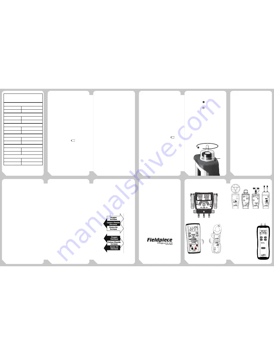
Battery Replacement
When the meter displays
the
battery should be replaced. Turn your
SOX3 off and replace with 9V battery.
O
2
Sensor Replacement
The SOX3 uses an oxygen smart
sensor. The
Press for 1 Sec to Exit
PRESS FOR
1 SECOND
FUEL
ON/OFF
MAX/MIN
AUTO-OFF
°F
°C
MEASURE/HOLD
°C
°F
HOLD
APO
%
MAX MIN
%
CO
2
EA
MAX
SET
icon indicates
approximate life remaining on the
sensor. When
Press for 1 Sec to Exit
PRESS FOR
1 SECOND
FUEL
ON/OFF
MAX/MIN
AUTO-OFF
°F
°C
MEASURE/HOLD
°C
°F
HOLD
APO
%
MAX MIN
%
CO
2
EA
MAX
SET
is shown replace
sensor.
1. Remove sensor cap by twisting CCW
slightly and then pulling.
2. Pull out old sensor.
3. Align plug of new sensor and care-
fully press into place.
To obtain an SOX3 replacement
oxygen sensor (model# RS02) contact
your local distributor.
Limited Warranty
This meter is warranted against
defects in material or workmanship
for one year from date of purchase.
Fieldpiece will replace or repair the
defective unit, at its option, subject
to verification of the defect.
This warranty does not apply
to defects resulting from abuse,
neglect, accident, unauthorized
repair, alteration, or unreasonable use
of the instrument.
Any implied warranties arising
from the sale of a Fieldpiece product,
including but not limited to implied
warranties of merchantability and
fitness for a particular purpose, are
limited to the above. Fieldpiece shall
not be liable for loss of use of the
instrument or other incidental or
consequential damages, expenses, or
economic loss, or for any claim of such
damage, expenses, or economic loss.
State laws var y. The above
limitations or exclusions may not
apply to you.
Combustion Basics
Combustion is the rapid oxidation
of fuel. Oxygen from air (20.9%
oxygen & 79.1% nitrogen) is used to
burn fuel which produces heat. The
appliances installed and serviced by
technicians rely on clean efficient
flames to produce the energy needed
to heat homes, water, etc. Combustion
testing is necessary to maximize
the efficiency of the combustion
systems and to minimize the harmful
emissions produced such as carbon
monoxide and carbon dioxide. Proper
tuning of the combustion process
by combustion testing reduces
the production of harmful carbon
monoxide and decreases the amount
of fuel burned due to increase in
efficiency.
Combustion efficiency can typically
be increased by creating a more
balanced air to fuel ratio. The ratio of
air to fuel determines how much CO
2
is produced and how efficient the
flame is.
Tuning the O
2
, CO
2
excess air, stack
temperature, and temperature rise to
match the appliance manufacturers
specifications will increase the
efficiency and help to maximize the
performance and life expectancy of
the equipment.
A properly tuned natural gas
appliance will have between 6-9 O
2
%
in the flue while an oil appliance will
have 3-7 O
2
%.
Adjustments to the combustion
process ensures that the highest
combustion efficiency is safely
achieved, thereby reducing the overall
amount of fuel used in producing the
energy needed. It is still necessary to
test and adjust the appliance to the
manufacturers’ specification for airflow
in the duct system, temperature
rise across the heat exchanger and
anything else that may need testing.
Testing and balancing appliances to
meet manufacturers’ specifications
helps to ensure maximum system
efficiency and equipment longevity.
Combustion testing does not take
into account start up losses, standby
losses, cabinet/boiler body losses, or
distribution losses in ducts or piping.
The diagram below is a simplified
representation of the relationship
between the various combustion
measurables, and how a change in
one parameter affects the others.
Courtesy of Erik Rasmussen ESCO Press 2007.
For Service
In the USA, call Fieldpiece
Instruments for one-price-fix-all out of
warranty service pricing. Send check or
money order for the amount quoted.
Send the meter freight prepaid to
Fieldpiece Instruments. Send proof
of date and location of purchase for
in-warranty service. The meter will be
repaired or replaced, at the option of
Fieldpiece, and returned via least cost
transportation. Outside of the USA,
please visit www.fieldpiece.com for
service contact information.
www.fieldpiece.com
©Fieldpiece Instruments, Inc 2012; v10
More Instruments
from Fieldpiece
Specifications
Sensor Type
: Highly accurate oxygen sensor.
Operating environment
: 32 to 122°F (0 to 50°C) at
<75% R.H.
Storage environment
: -4 to 140°F (-20 to 60°C) at
<80% R.H. with battery removed from meter.
Temperature Coefficient
: 0.1 times the applicable
accuracy per ° from 32°F to 64°F and 82°F to 122°F
(0 to 18°C and 28 to 50°C)
Battery
: 9V.
Battery Life
: 28 hours typical alkaline.
Auto Power off
: After 15 minutes.
Accuracy
: Stated accuracy at 23°C±5°C, <75% R.H.
Dimensions
: 45.0mm(H) x 69.8mm(W) x
211.7mm(D).
Weight
: approx. 579.7g with battery.
Display
: 4 digit liquid crystal display(LCD) with
maximum reading of 9999.
Low battery indication
: The
is displayed
when the voltage drops below the operating level.
1
2
Air Velocity
& Temperature
Head
English
READ
LO BATT
ON
LCD X
100
Average
(16 sec)
Metric
Real
time
AAV3
AUTO-
OFF
English
Metric
Ft/min
M/s
KM/hr
MPH
ºF
ºC
OFF
ADMN2
Dual-Port
Manometer
Accessory
Head
P1
P2
P1-P2
ON
0.1
ENGLISH
METRIC
0.01
(LCD/10)
Lo Batt
Resolution
ZERO
AUTO
OFF
P1
P2
T1
T2
Atmospheric
Pressure
Superheat
Subcooling
T1 T2 Direct
Saturation
Target
Superheat
CAL
CAL
CAL
CAL
Test
Pressure
AUTO
OFF
Refrigerant
ON/OFF
Enter
Units
Alarm
Digital Ma Vacuum Gauge
SMAN3
ODDB
HH:MM:SS
Psig
Kpa
inHg
cmHg
Psig
Kpa
inHg
cmHg
SHT1
VSAT
APO
Microns
HiLo
Set
Stable
Alarm
IDWB
Target SH
R-
°F°C
SCT2
LSAT
°F°C
°F°C
CAT.III
300V
400A
CLAMP
ACH4
AC Current
Clamp
1AAC / 1mVAC
400AAC MAX
!
ET2W
LO BATT
SEND
RECEIVE
ON
AC
DC
Wireless
Transmitter
SYNC
FUSED
200mA
MAX
FUSED
30V
MAX
WIRELESS
ENABLED
MAX/MIN
SYNC
HOLD
CAT.III
MAX
600V
15 SEC FOR 500mV
RANGE
AUTO-OFF
500
600
600
50
5000m
500m
500µ
50m
200m
200m
500m
5000m
50m
50500
500µ
500
750
500
1400
200
2K
200
20M
2K
200K
20
RECV
T2
T2
T2
T2
T2
T2
T2
T2
T2
T2
T2
T2
T2
T2
T2
T2
T2
T2
T2
P1
P1
P2
ZERO
HOLD
UNIT
ON/OFF
P2
88.88
APO
88.88
inWC
mmWC
mbar
psi
HOLD
PRESS FOR 1 SECOND
AUTO-OFF
BATTERY
CHECK
Digital Refrigerant Manifolds
Accessory Heads
Wireless Measurements
Dual-Port Manometer
Typical Recommended
Flue Gas Measurements
Atmospheric Fan Assisted Natural Gas or LPG
Oxygen (O
2
)
6 to 9%
Stack Temperature
325 to 500°F
Condensing Natural Gas or LPG
Oxygen (O
2
)
6 to 9%
Stack Temperature
90 to 140°F
Natural Gas/LPG Power Burners
Oxygen (O
2
)
3 to 6%
Stack Temperature
275 to 500°F
Fuel Oil Flame Retention Power Burners
Oxygen (O
2
)
3 to 7%
Stack Temperature
325 to 500°F
Fuel Oil Non-Flame Retention Power Burners
Oxygen (O
2
)
6 to 9%
Stack Temperature
400 to 600°F
Condensing Oil
Oxygen (O
2
)
3 to 7%
Stack Temperature
90 to 140°F
Table 2.


