page 11 of 16
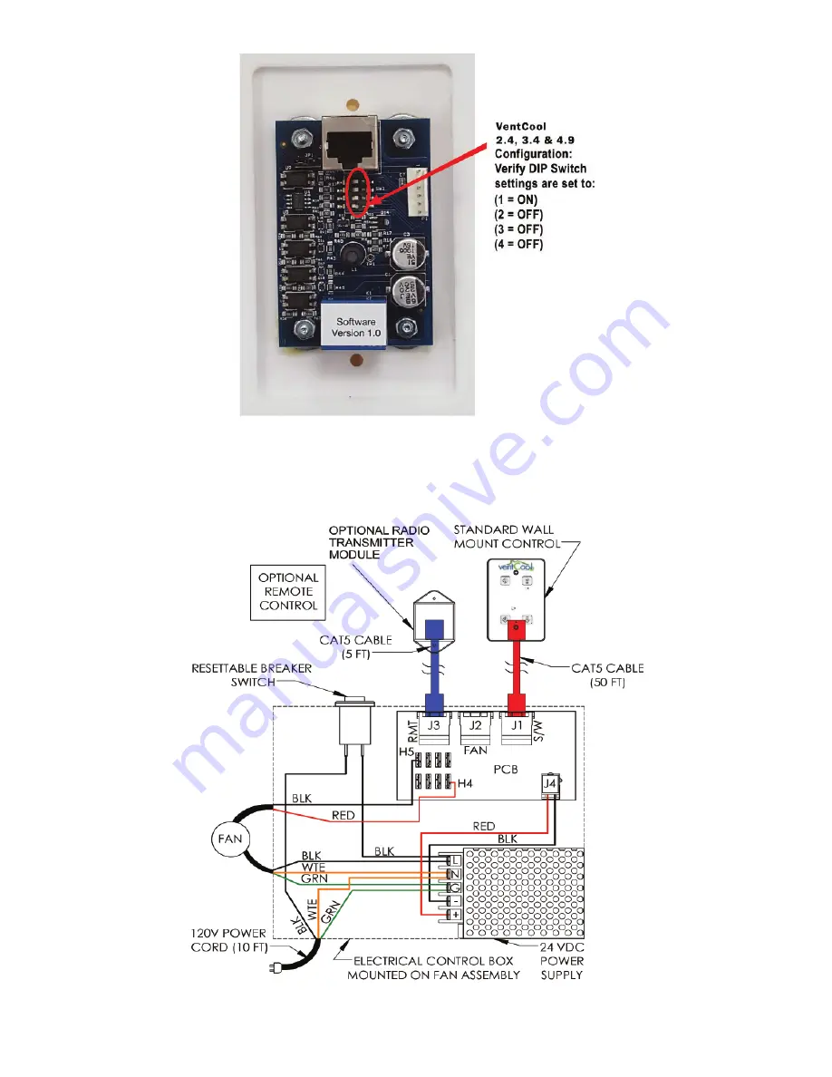
FIGURE 15: Wall Switch DIP Switch Settings
(Rear Surface of Display Switch)
Figure 16 shows the generic wiring schematic of the VentCool 2.4, 3.4 and 4.9 units.
FIGURE 16: VentCool 2.4, 3.4 & 4.9 Wiring Diagram
P/N:
78030007034
P/N 780100500 05/19 Rev B


