Page 3
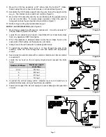
9. Mount the VRV tee assembly or 90° elbow onto the Air Boot™ intake.
Fasten using three (3) sheet metal screws on all joints (See Figure 5).
10. Assemble the VRV balance weight onto the gate. Screw the weight all the
way in. Then attach lock nut and knurl nut (See Figure 6).
11. Mount the VRV assembly onto the tee and fasten with the supplied screw
and nut in collar tabs. To ensure proper operation, Check the gate for
being level across the pivot points and plumb (See Figure 7).
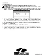
12. Refer to Figure 8 for general installation layout.
A
IR
D
UCT AND
A
IR
I
NTAKE
H
OOD
(See Figure 8)
1. Mount the air intake hood through an outside wall. It must be at least 12”
(inches) ABOVE grade or snow line.
2. Locate the air intake hood at least 3’ (feet) BELOW (or 6 feet horizontally
from) any appliance VENT termination.
3. When the appliance is sidewall vented, locate the air intake hood on the
same side of the building as the appliance vent outlet.
4. Always mount the air hood with the intake pointed down.
5. To install the air intake hood, cut a 4 ¼” hole through the side of the
building. Slide the hood through the wall and fasten with appropriate
screws.
6. Seal around the exterior plate with an exterior rated caulk, silicone sealant
or equivalent.
7. Locate the air hood so the air piping length doesn’t exceed the limits
below:
Number of Elbows
Maximum Length
of Air Pipe
2 to 4
35 Feet
5
28 Feet
6
21 Feet
7
14 Feet
8. Construct the air duct piping with 4” diameter dryer vent or aluminum or
galvanized steel pipe, using as few elbows as possible.
9. Fasten and support the air duct piping to prevent damage and separation
of joints.
Figure 7
Figure 6
Figure 5
Figure 8


