


Reproduction forbidden without Fibocom Wireless Inc. written authorization - All Rights Reserved.
L830-EB-11 Hardware User Manual
Page 15 of 39
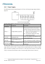
3.2.1 Power Supply
The L830 module should be powered through the +3.3V pins, and the power supply design is shown in
Figure 3-2:
Figure 3-2 Power Supply Design
The filter capacitor design for power supply as shown in the following table:
Recommended
capacitance
Application
Description
220uF x 2
Voltage-stabilizing capacitors
Reduce power fluctuations of the module in
operation, requiring capacitors with low ESR.
LDO or DC/DC power supply requires the
capacitor of no less than 220uF
The capacitor for battery power supply
can be reduced to 100uF
1uF,100nF
Digital signal noise
Filter out the interference generated from the
clock and digital signals
39pF,33pF
700,800,900 MHz frequency
band
Filter out low frequency band RF interference
18pF,8.2pF,6.8pF
1800,2100,2600MHz frequency
band
Filter out medium/high frequency band RF
interference
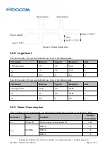
The stable power supply can ensure the normal operation of L830 module; and the ripple of the power
supply should be less than 300mV in design. When the module operates with the maximum emission
power, the maximum operating current can reach 1A, so the power source should be not lower than
3.135V, or the module may shut down or reboot. The power supply limits are shown in Figure 3-3:


