background image

3 Product Overview

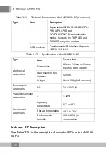
Table 3.20

Specifications of the AN5506-04-FS

Category

Item

Description

Mechanical
parameters

Dimensions

36mm × 211mm × 154mm
(height x width x depth)

Wall mounting hole
distance

121mm

Weight

About 409g (5dB antenna)

Power supply
parameter

DC

DC 12 V/1.5A

Power
consumption
parameter

-

12W

Environment
parameters

Operating temperature

-5

to 45

Storage temperature

-40

to 70

Environmental humidity

10% to 90% (no
condensation)

Indicator LED Description

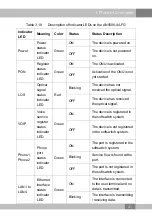
See Table 3.21 for the description of indicator LEDs on the AN5506-
04-FS.

Table 3.21

Description of Indicator LEDs on the AN5506-04-FS

Indicator
LED

Meaning

Color

Status

Status Description

Power

Power
status
indicator
LED

Green

ON

The device is powered
on.

OFF

The device is not
powered on.

48

Summary of Contents for AN5506-04 Series

Page 1: ...An Expert in Optical Communications Product Manual AN5506 04 Series GPON Optical Network Unit Version A Code MN000002260 Date May 2015 FiberHome Telecommunication Technologies Co Ltd ...

Page 2: ...ed in this document are used for identification purposes only and are trademarks or registered trademarks of their respective holders All rights redserved No part of this document including the electronic version may be reproduced or transmitted in any form or by any means without prior written permission from FiberHome Information in this document is subject to change without notice ...

Page 3: ...tion to the AN5506 04 F 27 3 6 Introduction to the AN5506 04 FG 34 3 7 Introduction to the AN5506 04 FS 42 3 8 Introduction to the AN5506 04 GG 51 4 Web Configuration Guide 60 4 1 Logging into Web GUI Locally 60 4 2 Status 67 4 2 1 Device Information 67 4 2 2 WAN Side Status 68 4 2 3 LAN Side Status 68 4 2 4 Optical Power Status 69 4 2 5 Voice Status 70 4 2 6 Wireless Network Status 70 4 3 Network...

Page 4: ...onfiguration 107 4 4 6 DDOS 109 4 4 7 HTTPS 110 4 5 Application 110 4 5 1 VPN 111 4 5 2 DDNS 111 4 5 3 Port Forwarding 113 4 5 4 Port Triggering 114 4 5 5 NAT 116 4 5 6 UPNP 117 4 5 7 DMZ 118 4 5 8 Network Diagnosis 119 4 6 Management 120 4 6 1 User Management 120 4 6 2 Device Management 121 4 6 3 Log 127 5 Handling Common Problems 129 5 1 The Power Indicator LED Remaining Off 129 5 2 The PON Indi...

Page 5: ...5 3 The LOS Indicator LED Keeping Blinking 129 5 4 LAN Indicator LED Remaining Off 130 5 5 Failing to Detect ONU Using Wi Fi 130 Appendix A Standard and Protocol 132 ...

Page 6: ......

Page 7: ...ables If any of them is damaged replace it immediately u Use the power supply adapter provided in the package only Using other adapters may cause equipment damage or operation failures u Install the equipment in a well ventilated environment without high temperatures or direct sunlight to protect the equipment and its components from overheating which can result in damage u Disconnect the power in...

Page 8: ...by the AN5506 04 Series ONUs Table 2 1 Interfaces Supported by the ONUs ONU Type Ethernet Interface Quantity Phone Interface Quantity Wi Fi Inter face USB Interface Quantity CATV Inter face Quantity AN5506 04 A 4 GE AN5506 04 B 4 GE 2 AN5506 04 CG 4 GE 2 1 1 AN5506 04 DG 4 GE 1 AN5506 04 F 4 FE 2 1 AN5506 04 FG 4 GE 2 1 AN5506 04 FS 4 GE 2 1 AN5506 04 GG 4 GE 2 1 1 Table 2 2 lists the service type...

Page 9: ... supported AN5506 04 B Supported Supported Supported Not supported AN5506 04 CG Supported Supported Supported Not supported AN5506 04 DG Supported Supported Not supported Supported AN5506 04 F Supported Supported Supported Supported AN5506 04 FG Supported Supported Supported Supported AN5506 04 FS Supported Supported Supported Supported AN5506 04 GG Supported Supported Supported Supported 3 ...

Page 10: ...06 04 A is an FTTH type GPON ONU It provides users with communication and entertainment services in the form of data video and so on to meet the integrated access demand of families and small scaled enterprises Appearance The overall appearance of the AN5506 04 A is shown in Figure 3 1 Figure 3 1 Overall Appearance of the AN5506 04 A The rear panel of the AN5506 04 A is shown in Figure 3 2 4 ...

Page 11: ...em Description Service parame ters VLAN Supports the IEEE 802 1Q VLAN standard Supports joining 802 1Q VLAN in tag untag mode Supports up to 4095 VLANs Multicast Supports the IGMP Snooping protocol Supports IGMP v1 v2 v3 Wire speed forward ing Supports Layer 2 Layer 3 wire speed forwarding IP Supports the IPv4 v6 dual stack Security Supports the packet filtering MAC address filtering and URL filte...

Page 12: ...y and flexible mapping of 802 1p values in packets Supports three queue scheduling modes PQ WRR and PQ WRR supports configuring the weight of the scheduled queue so as to guarantee the service quality of high QoS services such as video in the multi service environment Network side interface GPON interface Provides one GPON interface SC UPC or SC APC interface supporting transmission distance up to...

Page 13: ...parameters 6 1W Environment parameters Operating temperature 5 to 45 Storage temperature 40 to 70 Environmental humidity 10 to 90 no condensation Indicator LED Description See Table 3 3 for the description of indicator LEDs on the AN5506 04 A Table 3 3 Description of Indicator LEDs on the AN5506 04 A Indicator LED Meaning Color Status Status Description PON Register status indicator LED Green ON T...

Page 14: ...ser terminal and no data is transmitted Blinking The interface is transmitting receiving data OFF The interface is not connected to the user terminal Power Power status indicator LED Green ON The device is powered on OFF The device is not powered on 3 2 Introduction to the AN5506 04 B The AN5506 04 B is an FTTH type GPON ONU It provides users with communication and entertainment services in the fo...

Page 15: ...el of the AN5506 04 B Equipment Specifications The AN5506 04 B specifications include technical parameters and specifications See Table 3 4 for the technical parameters and see Table 3 5 for the specifications Table 3 4 Technical Parameters of the AN5506 04 B Type Item Description Service parame ters Voice Supports the protocols H 248 and SIP 9 ...

Page 16: ... forwarding IP Supports the IPv4 v6 dual stack Security Supports the packet filtering MAC address filtering and URL filtering Supports protection against illegal message DoS ARP attacks supports suppression of broadcast storms Supports obtaining user IP address in DHCP mode supports reporting physical location of the Ethernet interface using DHCP Option82 Supports obtaining user IP address in the ...

Page 17: ...es one GPON interface SC UPC or SC APC interface supporting transmission distance up to 20km and complying with the ITU T G 984 standard Supports Class B with receiving sensitivity less than 29 dBm User side interface LAN interface Provides four LAN interfaces RJ 45 interfaces supporting full duplex or half duplex and 10 100 1000M auto negotiation The maximum transmission distance is 100m MAC addr...

Page 18: ...iption of indicator LEDs on the AN5506 04 B Table 3 6 Description of Indicator LEDs on the AN5506 04 B Indicator LED Meaning Color Status Status Description PON Register status indicator LED Green ON The ONU is activated OFF Activation of the ONU is not yet started LOS Optical signal status indicator LED Red Blinking The device has not received the optical signal OFF The device has received the op...

Page 19: ...hone2 Phone port status indicator LED Green ON The port is registered in the softswitch system Blinking Service flow is found at the port OFF The port is not registered in the softswitch system VoIP Voice service register status indicator LED Green ON The device is registered in the softswitch system OFF The device is not registered in the softswitch system Power Power status indicator LED Green O...

Page 20: ...ice video and so on to meet the integrated access demand of families and small scaled enterprises Appearance The overall appearance of the AN5506 04 CG is shown in Figure 3 5 Figure 3 5 Overall Appearance of the AN5506 04 CG The rear panel of the AN5506 04 CG is shown in Figure 3 6 Figure 3 6 Rear Panel of the AN5506 04 CG The side panel of the AN5506 04 CG is shown in Figure 3 7 14 ...

Page 21: ...Description Service parame ters Voice Supports the protocols H 248 and SIP Supports the speech encoding modes such as G 711 G 723 and G 729 VLAN Supports the IEEE 802 1Q VLAN standard Supports joining 802 1Q VLAN in tag untag mode Supports up to 4095 VLANs Multicast Supports the IGMP Snooping protocol Supports IGMP v1 v2 v3 Wire speed forward ing Supports Layer 2 Layer 3 wire speed forwarding IP S...

Page 22: ...upports global configuration of queue priority and flexible mapping of 802 1p values in packets Supports three queue scheduling modes PQ WRR and PQ WRR supports configuring the weight of the scheduled queue so as to guarantee the service quality of high QoS services such as voice and video in the multi service environment Network side interface GPON interface Provides one GPON interface SC UPC or ...

Page 23: ...mV Table 3 8 Specifications of the AN5506 04 CG Type Item Description Mechanical parameters Dimensions 36mm 211mm 154mm height x width x depth Wall mounting hole distance 121mm Weight About 418g Power supply parameters DC DC 12 V 1 5A Power consumption parameters 11 5W Environment parameters Operating temperature 5 to 45 Storage temperature 40 to 70 Environmental humidity 10 to 90 no condensation ...

Page 24: ... yet started LOS Optical signal status indicator LED Red Blinking The device has not received the optical signal OFF The device has received the optical signal VOIP Voice service register status indicator LED Green ON The device is registered in the softswitch system OFF The device is not registered in the softswitch system Phone1 Phone2 Phone port status indicator LED Green ON The port is registe...

Page 25: ...mitted Blinking The interface is transmitting receiving data OFF The interface is not connected to the user terminal CATV CATV interface indicator LED Green ON The CATV function is enabled and the CATV signal can be received normally Blinking The CATV function is enabled and the CATV signal is poor OFF The CATV function is not enabled the CATV signal is not received or the signal is poor USB USB i...

Page 26: ...rovides users with communication and entertainment services in the form of data video and so on to meet the integrated access demand of families and small scaled enterprises Appearance The overall appearance of the AN5506 04 DG is shown in Figure 3 8 Figure 3 8 Overall Appearance of the AN5506 04 DG 20 ...

Page 27: ...3 Product Overview The rear panel of the AN5506 04 DG is shown in Figure 3 9 Figure 3 9 Rear Panel of the AN5506 04 DG The side panel of the AN5506 04 DG is shown in Figure 3 10 21 ...

Page 28: ...s See Table 3 10 for the technical parameters and see Table 3 11 for the specifications Table 3 10 Technical Parameters of the AN5506 04 DG Type Item Description Service parame ters VLAN Supports the IEEE 802 1Q VLAN standard Supports joining 802 1Q VLAN in tag untag mode Supports up to 4095 VLANs Multicast Supports IGMP Snooping protocol Supports IGMP v1 v2 v3 22 ...

Page 29: ...ts reporting physical location of the Ethernet interface using DHCP Option82 Supports obtaining user IP address using PPPoE mode supports the PPPoE function used to identify users accurately Supports downlink data using the AES 128 algorithm for encryption QoS Supports the ACL function to match traffic based on the ACL rules Supports global configuration of queue priority and flexible mapping of 8...

Page 30: ... 10 100 1000M auto negotiation The maximum transmission distance is 100m MAC address capacity 1K Wi Fi Interface 2 4GHz supports the 802 11b g n mode Supports four SSIDs and thirteen working channels supports automatic rate adjustment and launched power adjustment Supports the OPEN SHARED WPA PSK WPA2 PSK and WPAPSKWPA2PSK authentication modes Supports the TKIP AES and TKIPAES encryption modes USB...

Page 31: ... 3 12 for the description of indicator LEDs on the AN5506 04 DG Table 3 12 Description of Indicator LEDs on the AN5506 04 DG Indicator LED Meaning Color Status Status Description Power Power status indicator LED Green ON The device is powered on OFF The device is not powered on PON Register status indicator LED Green ON The ONU is activated OFF Activation of the ONU is not yet started LOS Optical ...

Page 32: ...ting receiving data OFF The interface is not connected to the user terminal USB USB indicator LED Green ON The USB is connected OFF The USB is not connected WIFI Wireless signal status indicator LED Green ON The wireless interface is enabled Blinking The interface is transmitting receiving data OFF The wireless interface is disabled WPS WPS status indicator LED Green ON WPS is enabled and connecte...

Page 33: ...and entertainment services in the form of data voice video and so on to meet the integrated access demand of families and small scaled enterprises Appearance The overall appearance of the AN5506 04 F is shown in Figure 3 11 Figure 3 11 Overall Appearance of the AN5506 04 F The rear panel of the AN5506 04 F is shown in Figure 3 12 27 ...

Page 34: ...3 Product Overview Figure 3 12 Rear Panel of the AN5506 04 F The side panel of the AN5506 04 F is shown in Figure 3 13 28 ...

Page 35: ...le 3 13 for the technical parameters and see Table 3 14 for the specifications Table 3 13 Technical Parameters of the AN5506 04 F Type Item Description Service parame ters Voice Supports the protocols H 248 and SIP Supports the speech encoding modes such as G 711 G 723 and G 729 VLAN Supports the IEEE 802 1Q VLAN standard Supports joining 802 1Q VLAN in tag untag mode 29 ...

Page 36: ...upports protection against illegal message DoS ARP attacks supports suppression of broadcast storms Supports obtaining user IP address in DHCP mode supports reporting physical location of the Ethernet interface using DHCP Option82 Supports obtaining user IP address using PPPoE mode supports the PPPoE function used to identify users accurately Supports downlink data using the AES 128 algorithm for ...

Page 37: ...dard Supports Class B with receiving sensitivity less than 29 dBm User side interface LAN interface Provides four LAN interfaces RJ 45 interfaces supporting full duplex or half duplex and 10 100 auto negotiation The maximum transmission distance is 100m MAC address capacity 1K Phone interface Provides two phone interfaces RJ 11 interfaces Wi Fi Interface 2 4GHz supports the 802 11b g n mode Suppor...

Page 38: ...consumption parameters 12W Environment parameters Operating temperature 5 to 45 Storage temperature 40 to 70 Environmental humidity 10 to 90 no condensation Indicator LED Description See Table 3 15 for the description of indicator LEDs on the AN5506 04 F Table 3 15 Description of Indicator LEDs on the AN5506 04 F Indicator LED Meaning Color Status Status Description Power Power status indicator LE...

Page 39: ... the optical signal VOIP Voice service register status indicator LED Green ON The device is registered in the softswitch system OFF The device is not registered in the softswitch system Phone1 Phone2 Phone port status indicator LED Green ON The port is registered in the softswitch system Blinking Service flow is found at the port OFF The port is not registered in the softswitch system LAN1 to LAN4...

Page 40: ...ace is enabled Blinking The interface is transmitting receiving data OFF The wireless interface is disabled WPS WPS status indicator LED Green ON WPS is enabled and connected to the device Blinking WPS is in use for relevant negotiation OFF WPS is not enabled or not connected to device 3 6 Introduction to the AN5506 04 FG The AN5506 04 FG is an FTTH type GPON ONU It provides users with communicati...

Page 41: ...oduct Overview Appearance The overall appearance of the AN5506 04 FG is shown in Figure 3 14 Figure 3 14 Overall Appearance of the AN5506 04 FG The rear panel of the AN5506 04 FG is shown in Figure 3 15 35 ...

Page 42: ...3 Product Overview Figure 3 15 Rear Panel of the AN5506 04 FG The side panel of the AN5506 04 FG is shown in Figure 3 16 36 ...

Page 43: ...nd specifications See Table 3 16 for the technical parameters and see Table 3 17 for the specifications Table 3 16 Technical Parameters of the AN5506 04 FG Type Item Description Service parameters Voice Supports the protocols H 248 and SIP Supports the speech encoding modes such as G 711 G 723 and G 729 VLAN Supports the IEEE 802 1Q VLAN standard 37 ...

Page 44: ...d URL filtering Supports protection against illegal message DoS ARP attacks supports suppression of broadcast storms Supports obtaining user IP address using DHCP mode supports DHCP Option82 reporting the physical location information of the Ethernet interface Supports obtaining user IP address using PPPoE mode supports the PPPoE function used to identify users accurately Supports downlink data us...

Page 45: ...PC interface supporting transmission distance up to 20km and complying with the ITU T G 984 standard Supports Class B with receiving sensitivity less than 29 dBm User side interface LAN interface Provides four LAN interfaces RJ 45 interfaces supporting full duplex or half duplex and 10 100 1000M auto negotiation The maximum transmission distance is 100m MAC address capacity 1K Phone interface Prov...

Page 46: ...e 3 17 Specifications of the AN5506 04 FG Type Item Description Mechanical parameters Dimensions 36mm 211mm 154mm height x width x depth Wall mounting hole distance 121mm Weight About 409g 5dB antenna Power supply parameters DC DC 12 V 1 5A Power consumption parameters 12W Environment parameters Operating temperature 5 to 45 Storage temperature 40 to 70 Environmental humidity 10 to 90 no condensat...

Page 47: ...he optical signal OFF The device has received the optical signal VOIP Voice service register status indicator LED Green ON The device is registered in the softswitch system OFF The device is not registered in the softswitch system Phone1 Phone2 Phone port status indicator LED Green ON The port is registered in the softswitch system Blinking Service flow is found at the port OFF The port is not reg...

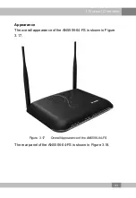
Page 48: ...ace is enabled Blinking The interface is transmitting receiving data OFF The wireless interface is disabled WPS WPS status indicator LED Green ON WPS is enabled and connected to the device Blinking WPS is in use for relevant negotiation OFF WPS is not enabled or not connected to device 3 7 Introduction to the AN5506 04 FS The AN5506 04 FS is an FTTH type GPON ONU It provides users with communicati...

Page 49: ...oduct Overview Appearance The overall appearance of the AN5506 04 FS is shown in Figure 3 17 Figure 3 17 Overall Appearance of the AN5506 04 FS The rear panel of the AN5506 04 FS is shown in Figure 3 18 43 ...

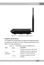
Page 50: ...3 Product Overview Figure 3 18 Rear Panel of the AN5506 04 FS The side panel of the AN5506 04 FS is shown in Figure 3 19 44 ...

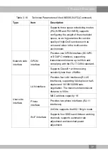
Page 51: ...3 19 for the technical parameters and see Table 3 20 for the specifications Table 3 19 Technical Parameters of the AN5506 04 FS Category Item Description Service parameters Voice Supports the protocols H 248 and SIP Supports the speech encoding modes such as G 711 G 723 and G 729 VLAN Supports the IEEE 802 1Q VLAN standard Supports joining 802 1Q VLAN in the tag untag mode 45 ...

Page 52: ...ng Supports protection against illegal message DoS ARP attacks supports suppression of broadcast storms Supports obtaining user IP address in DHCP mode supports reporting physical location of the Ethernet interface using DHCP Option82 Supports obtaining user IP address in the PPPoE mode supports the PPPoE function used to identify users accurately Supports encryption of downlink data using the AES...

Page 53: ...dard Supports Class B with receiving sensitivity less than 29 dBm User side interface LAN interface Provides four LAN interfaces RJ 45 interfaces supporting full duplex or half duplex and 10 100 1000M auto negotiation The maximum transmission distance is 100m MAC address capacity 1K Phone interface Provides two phone interfaces RJ 11 interfaces Wi Fi interface 2 4GHz supports the 802 11b g n mode ...

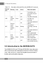
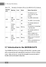
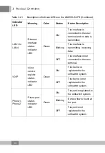
Page 54: ... consumption parameter 12W Environment parameters Operating temperature 5 to 45 Storage temperature 40 to 70 Environmental humidity 10 to 90 no condensation Indicator LED Description See Table 3 21 for the description of indicator LEDs on the AN5506 04 FS Table 3 21 Description of Indicator LEDs on the AN5506 04 FS Indicator LED Meaning Color Status Status Description Power Power status indicator ...

Page 55: ...king The device has not received the optical signal OFF The device has received the optical signal WIFI Wireless signal status indicator LED Green ON The wireless interface is enabled Blinking The interface is transmitting receiving data OFF The wireless interface is disabled WPS WPS status indicator LED Green ON WPS is enabled and connected to the device Blinking WPS is in use for relevant negoti...

Page 56: ... Blinking The interface is transmitting receiving data OFF The interface is not connected to the user terminal VOIP Voice service register status indicator LED Green ON The device is registered in the softswitch system OFF The device is not registered in the softswitch system Phone1 Phone2 Phone port status indicator LED Green ON The port is registered in the softswitch system Blinking Service flo...

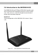
Page 57: ...des users with communication and entertainment services in the form of data voice video and so on to meet the integrated access demand of families and small scaled enterprises Appearance The overall appearance of the AN5506 04 GG is shown in Figure 3 20 Figure 3 20 Overall Appearance of the AN5506 04 GG 51 ...

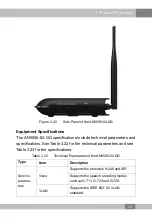
Page 58: ...3 Product Overview The rear panel of the AN5506 04 GG is shown in Figure 3 21 Figure 3 21 Rear Panel of the AN5506 04 GG The side panel of the AN5506 04 GG is shown in Figure 3 22 52 ...

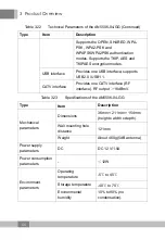
Page 59: ...d specifications See Table 3 22 for the technical parameters and see Table 3 23 for the specifications Table 3 22 Technical Parameters of the AN5506 04 GG Type Item Description Service parame ters Voice Supports the protocols H 248 and SIP Supports the speech encoding modes such as G 711 G 723 and G 729 VLAN Supports the IEEE 802 1Q VLAN standard 53 ...

Page 60: ...ltering and URL filtering Supports protection against illegal message DoS ARP attacks supports suppression of broadcast storms Supports obtaining user IP address in DHCP mode supports reporting physical location of the Ethernet interface using DHCP Option82 Supports obtaining user IP address in the PPPoE mode supports the PPPoE function used to identify users accurately Supports encryption of down...

Page 61: ...PC interface supporting transmission distance up to 20km and complying with the ITU T G 984 standard Supports Class B with receiving sensitivity less than 29 dBm User side interface LAN interface Provides four LAN interfaces RJ 45 interfaces supporting full duplex or half duplex and 10 100 1000M auto negotiation The maximum transmission distance is 100m MAC address capacity 1K Phone interface Prov...

Page 62: ...0 USB1 1 CATV interface Provides one CATV interface RF interface RF output 18dBmV Table 3 23 Specifications of the AN5506 04 GG Type Item Description Mechanical parameters Dimensions 36mm 211mm 154mm height x width x depth Wall mounting hole distance 121mm Weight About 460g 5dB antenna Power supply parameters DC DC 12 V 1 5A Power consumption parameters 12W Environment parameters Operating tempera...

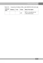
Page 63: ... ONU is activated OFF Activation of the ONU is not yet started LOS Optical signal status indicator LED Red Blinking The device has not received the optical signal OFF The device has received the optical signal VOIP Voice service register status indicator LED Green ON The device is registered in the softswitch system OFF The device is not registered in the softswitch system Phone1 Phone2 Phone port...

Page 64: ...een ON The CATV function is enabled and the CATV signal can be received normally Blinking The CATV function is enabled and the CATV signal is poor OFF The CATV function is not enabled the CATV signal is not received or the signal is poor USB USB indicator LED Green ON The USB is connected OFF The USB is not connected WIFI Wireless signal status indicator LED Green ON The wireless interface is enab...

Page 65: ...3 Product Overview Table 3 24 Description of Indicator LEDs on the AN5506 04 GG Continued Indicator LED Meaning Color Status Status Description OFF WPS is not enabled or not connected to device 59 ...

Page 66: ...he ONU Web GUI locally and introduces the configuration GUI layout Prerequisites u The ONU has connected with the computer correctly u The user computer is started normally u The ONU is started normally Press the ONU power button If the power indicator LED is ON the ONU is powered on successfully Planning Data Before setting the configuration environment prepare the data information as shown in Ta...

Page 67: ...t the bottom of the device Note The password is case sensitive Management IP address and subnet mask of the ONU Factory default value u IP address 192 168 1 1 u Subnet mask 255 255 255 0 Note Some operators have customized IP address requirement so the system default management IP address may be different from the IP address above In this case refer to the User Manual attached to the equipment or ...

Page 68: ...indows 7 operating system is as follows a In the Windows taskbar select Start Control Panel and click Network and Sharing Center b Click Local Area Connection to bring up the Local Area Connection Properties and click Properties c In the Local Area Connection Properties dialog box double click Internet Protocol 4 TCP IPv4 62 ...

Page 69: ...4 Web Configuration Guide d In the Internet Protocol 4 TCP IPv4 Properties dialog box set the IP address and subnet mask of the computer See Table 4 1 for the detailed values 63 ...

Page 70: ...Double click Network Connection to enter the network connection window b Right click Local Connection and select Properties from the shortcut menu to bring up the Local Connection Properties dialog box c Double click Internet Protocol TCP IP In the Internet Protocol TCP IP Properties dialog box that appears set the IP address and subnet mask of the computer See Table 4 1 for the detailed values 64...

Page 71: ...r username and password in the login dialog box Access the Web GUI after the password is authenticated Caution The system will log out automatically if no operation is performed in five minutes Web Configuration GUI Layout The Web configuration GUI comprises three parts as shown in Figure 4 1 u Navigation bar Click the link to enter the corresponding configuration management tab u Link bar Click t...

Page 72: ...e following illustrates how an administrator user admin of the AN5506 04 GG logs into the Web GUI version RP2560 The snapshot pictures for other devices may be a little different from the ones here The practical GUI shall prevail The configuration GUI for the administrator is different from that for common users u The administrator can view and configure all the node items in the Web GUI u The com...

Page 73: ...tus The following introduces how to view the ONU basic information including device information WAN side status LAN side status optical power status voice status and wireless network status in the Web GUI 4 2 1 Device Information Select State in the navigation bar and select Device Information in the left link bar to view the information such as the product name hardware version and software versi...

Page 74: ...ess and subnet mask of the WAN side See Figure 4 3 Figure 4 3 WAN Side Status 4 2 3 LAN Side Status Check the state information about the LAN interface and the DHCP client end LAN Side Status Select State in the navigation bar and select Lan State Lan State in the left link bar to view the information such as the IP address subnet mask service type and status of the LAN side See Figure 4 4 68 ...

Page 75: ...ew the information about the DHCP client end such as the IP address MAC address and hired time See Figure 4 5 Figure 4 5 DHCP User List 4 2 4 Optical Power Status Select State in the navigation bar and select Optical Power in the left link bar to view the optical module information such as the Tx optical power Rx optical power and working temperature See Figure 4 6 69 ...

Page 76: ...nk bar to view the information such as the the user status and phone number See Figure 4 7 Figure 4 7 Voice Status 4 2 6 Wireless Network Status Select State in the navigation bar Select Wireless State in the left link bar to view the information of the wireless network such as network mode band SSID and wireless packet statistics See Figure 4 8 70 ...

Page 77: ...roduces how to configure the WLAN LAN broadband DHCP server remote management authentication and IPv6 in the Web GUI 4 3 1 WLAN Settings The following introduces how to configure basic and advanced parameters of the wireless network WIFI control and view of WIFI user list on the Web page 71 ...

Page 78: ...Configuration of Wireless Network 2 Configure the basic parameters of the wireless network See Table 4 2 for the parameter description 3 Click Apply to save and apply the configuration Table 4 2 Basic Parameters of the Wireless Network Item Description Radio ON OFF Enables or disables the WLAN service RADIO ON the wireless network is enabled RADIO OFF the wireless network is disabled Network Mode ...

Page 79: ...t Frequency Bandwidth The width of wireless band The values include 20MHz 40MHz 20MHz and 40MHz The default setting is 20MHz 40MHz 4 3 1 2 Advanced Configuration Configure the parameters of the wireless network such as the SSID password security mode and algorithm 1 Select Network in the navigation bar and select Wlan Settings Advanced in the left link bar to open the advanced setting tab of the w...

Page 80: ... requesting to access the wireless network The options include OPEN SHARED WPA PSK WPA2 PSK and WPAPSKWPA2PSK u OPEN Unencrypted Any terminal can access to the wireless network so that the security cannot be guaranteed This mode is not advisable u SHARED Based on the WEP encryption protocol this mode uses the same key for the wireless access client end and the equipment side and provides the secur...

Page 81: ...r disable the WEP encryption when the network authentication mode is OPEN Default Key Select Key1 to Key4 that is select one of the four configured network keys This item should be configured when the authentica tion mode is OPEN and the WEP encryption is enabled or the authentica tion mode is SHARED WEP Key 1 to WEP Key 4 Enter the key value and select the key value type At least enter the item s...

Page 82: ...be invalid If users lose the customized wireless network account they can restore the factory default account long press the Reset button for at least 5s 4 3 1 3 WIFI Control Configure the parameters of the wireless network such as WIFI power and quantity of connected client ends 1 Select Network in the navigation bar and select Wlan Settings WIFI Control in the left link bar to open the WIFI cont...

Page 83: ...er of the wireless signal Larger value indicates wider signal coverage WIFI Connection Number The maximum quantity of client ends supported by SSID ranging from 0 to 32 4 3 1 4 WIFI User List Select Network in the navigation bar and select Wlan Settings WIFI Client List in the left link bar to view the list of client ends that connect to the ONU wireless network as shown in Figure 4 12 Figure 4 12...

Page 84: ...gs 2 Configure the management IP address and subnet mask at the LAN side See Table 4 5 for the parameter description 3 Click Apply to save and apply the configuration Table 4 5 Parameters of LAN Settings Item Description IP Address The management IP address at the LAN side of the ONU The default value is 192 168 1 1 Subnet Mask The subnet mask of the ONU for the LAN The default value is 255 255 25...

Page 85: ...adjustment range Click Apply to save and apply the configuration 3 Optional Click Reset to restore to the default RF output level adjustment range 4 3 3 Broadband Settings Select different WAN connections for different network environment or configure corresponding parameters for the selected WAN connection 1 Select Network in the navigation bar and select BroadBand Settings in the left link bar t...

Page 86: ... Click Apply to save and apply the configuration Table 4 6 Parameters for Broadband Settings Item Description Service Type Select the WAN port service type u TR069 this connection is only applicable for TR069 u INTERNET this connection is only applicable for Internet access u TR069_INTERNET this connection is applicable for both TR069 and Internet access 80 ...

Page 87: ...T TR069_INTERNET VOIP_INTERNETor Other u Route the Layer 3 router connection mode This connection mode can be used for all the service types except for multicast VLAN ID Sets the VLAN ID of the WAN connection The VLAN ID value here should be consistent with that on the user side of the OLT Priority Sets the priority of the VLAN Nat Enables or disables the NAT function Users need to configure this ...

Page 88: ...de at the WAN side of the ONU The options include DHCP static and PPPoE u DHCP Obtaining the IP address dynamically u Static Setting the IP address in a static mode u PPPoE PPPoE dialing mode This item should be set if the connection type is Route User Name Enter the username provided by ISP This item should be set if the WAN IP Mode is set to PPPoE Pass word Enter the password provided by ISP Ope...

Page 89: ...f the active DNS server provided by ISP Second ary DNS Server Enter the IP address of the standby DNS server provided by ISP IPv6 Address Enter the static IPv6 address at the WAN side provided by ISP This item should be set when IPv6 is enabled and the WAN IP Mode is set to static IPv6 Prefix Length Enter the static IPv6 address prefix length at the WAN side provided by ISP Default Gateway Enter t...

Page 90: ...set to DHCP or PPPoE 4 3 4 DHCP Server Using the DHCP function the ONU can distribute the network parameters such as IP address gateway and DNS server IP address to the devices such as computer within the LAN Users can manage the IP addresses collectively using the function 1 Select Network in the navigation bar Select DHCP Server from the left link bar to open the DHCP server configuration tab as...

Page 91: ... terminals connected to the ONU cannot obtain the private network IP address using the DHCP DHCP Start IP The starting IP address of the IP address pool of the DHCP server Note The IP address set here should be in the same network segment with the IP address set in LAN Settings otherwise the DHCP server will not operate normally DHCP End IP The end IP address of the IP address pool of the DHCP ser...

Page 92: ...perty terminal distributed by the DHCP server 4 3 5 Remote Management The TR 069 protocol is a communication specification between the terminal equipment and the ACS If the TR 069 automatic service issue is enabled for the ISP the configuration of terminals will be issued automatically by the ACS The network parameters can be configured automatically using the TR 069 function provided that the ACS...

Page 93: ...les or disables the TR069 function After the aforesaid operation click the Apply button to validate the configuration URL The ACS server path provided by ISP for the ONU to send the connection request Username The username for the ONU to register on the ACS Password The password for the ONU to register on the ACS Connection Request Path The URL used for connecting the ACS to the ONU Set this item ...

Page 94: ...the ONU and the ACS After the Inform message is enabled the ONU will authenticate and connect with the ACS at the end of each informing interval reporting the Inform messages for information exchange between them Inform Interval After the Inform message is enabled set the time interval of sending Inform messages unit s Get RPC Methods Click this button and the current ONU and ACS will discover the...

Page 95: ...ic SN Sets the logical SN username This item is configurable when the ONU uses the SN authentication Logic Password Sets the logical SN password Password authentication Sets the authentication password when the ONU is authenticated by password 4 3 7 IPV6 Configure the IPv6 static routing 1 Select Network in the navigation bar Select IPV6 from the left link bar and click Add in the information bar ...

Page 96: ...ration Table 4 10 Parameters for the IPv6 Static Routing Item Description DstPrefix The destination IP address to be accessed by the host Nexthop The IP address of the next hop gateway WAN The WAN port passed by the static routing Select the available WAN port 4 4 Security The following introduces how to configure the firewall remote control route QOS WPS ACL configuration DDOS and HTTPS in Web GU...

Page 97: ... Mac filtering 4 4 1 1 Firewall Enabling Enabling firewall can prevent the malicious access to the WAN port of the ONU 1 Select Security in the navigation bar and select Firewall Firewall Enable in the left link bar to open the firewall enabling tab as shown in Figure 4 20 Figure 4 20 Firewall Enabling 2 Select to Enable or Disable the firewall as required 3 Click Apply to save and apply the confi...

Page 98: ...he pre set rules will take effect 1 Select Security in the navigation bar and select Firewall IP Filtering in the left link bar Click Add to open the filtering rule list configuration tab as shown in Figure 4 21 Figure 4 21 IP Filtering 2 Configure the parameters relevant to filtering as required Table 4 11 describes the parameters 3 Click Apply to save and apply the configuration 92 ...

Page 99: ...o pass u Blacklist indicates that the data complying with the rules in the filtering rule table will not be allowed to pass Direction Sets the direction of the filtering rule u LAN WAN uplink direction u WAN LAN downlink direction Src IP Enter the IP address at the LAN side if the direction is LAN WAN Enter the IP address at the WAN side if the direction is WAN LAN Src Port The port range of the s...

Page 100: ...bled the pre set rules will take effect 1 Select Security in the navigation bar and select Firewall IPv6 Filtering in the left link bar Then click Add to open the IPv6 filtering rule list configuration tab as shown in Figure 4 22 Figure 4 22 IPv6 Filtering 2 Configure the parameters relevant to filtering as required Table 4 12 describes the parameters 3 Click Apply to save and apply the configurat...

Page 101: ...icates that the data complying with the rules in the filtering rule table will not be allowed to pass Direction Sets the direction of the filtering rule u LAN WAN uplink direction u WAN LAN downlink direction Src IPv6 Enter the IPv6 address at the LAN side if the direction is set to LAN WAN Enter the IPv6 address at the WAN side if the direction is set to WAN LAN Src Port The port range of the sou...

Page 102: ...ke effect and the domain names that meet the filtering conditions will be filtered 1 Select Security in the navigation bar and select Firewall URL Filtering in the left link bar and then click Add to open the URL filtering table configuration tab as shown in Figure 4 23 Figure 4 23 URL Filtering 2 Configure the parameters relevant to filtering as required Table 4 13 describes the parameters 3 Clic...

Page 103: ...he filtering rule table will be allowed to pass u Blacklist indicates that the data complying with the rules defined in the filtering rule table will not be allowed to pass URL Address The URL address accessed by users Start Time The starting time of the filtering rule End Time The ending time of the filtering rule Enable Enables or disables this filtering rule The options include Disable and Enab...

Page 104: ...bid or allow the user device configured with the MAC address to obtain an IP address in the DHCP mode to prevent DOS attacks After the firewall is enabled the pre set rules will take effect 1 Select Security in the navigation bar and select Firewall DHCP filter in the left link bar and then click Add to open the anti DOS attack configuration tab as shown in Figure 4 25 Figure 4 25 DHCP Filtering 9...

Page 105: ...he IP address using the DHCP u Blacklist indicates forbidding the device configured with the MAC address to obtain the IP address using the DHCP MAC Address The MAC address of the user device subject to the DHCP filtering rule 4 4 1 7 MAC Address Filtering One user device may have multiple IP addresses but only one MAC address The user device access authority in the LAN can be controlled effective...

Page 106: ...ltering Enable Enables or disables the MAC address filtering function After setting click Apply below to take effect MAC Filtering Blacklist Whitelist Select the filtering mode The white list and black list modes are global configuration which cannot be enabled simultaneously u Whitelist indicates that the data complying with the rules defined in the filtering rule table will be allowed to pass u ...

Page 107: ...e Disable and Enable 4 4 1 8 IPv6 Mac Filtering One user device may have multiple IPv6 addresses but only one MAC address The user device access authority in the LAN can be controlled effectively by setting the MAC address filtering After the fire wall is enabled the pre set rules will take effect and the MAC addresses that meet the filtering conditions will be filtered 1 Select Security in the na...

Page 108: ...Filtering Enable Enables or disables the MAC address filtering function After setting click Apply below to take effect MAC Filtering Blacklist Whitelist Select the filtering mode The white list and black list modes are global configuration which cannot be enabled simultaneously u Whitelist indicates that the data complying with the rules defined in the filtering rule table will be allowed to pass ...

Page 109: ...nclude Disable and Enable 4 4 2 Remote Control Enable or disable the remote access control If the remote control is disabled the PCs in the Internet cannot access the Web GUI of the ONU using the IP addresses at the WAN side if enabled the PCs in the Internet can access the Web GUI 1 Select Security in the navigation bar and select Remote Control in the left link bar to open the remote control con...

Page 110: ...29 Figure 4 29 Route QoS Enabling 2 Select to Enable or Disable the route QOS function as required 3 Click Apply to save and apply the configuration 4 4 3 2 Route QOS Configuration While configuring the route QOS parameters user can classify the queues based on priority and process the messages with high priority first when system congestion occurs 1 Select Security in the navigation bar and selec...

Page 111: ... 17 Parameters of Route QoS Configuration Item Description Type Select the priority type Priority Sets the priority value The DSCP priority value ranges from 0 to 63 the 802 1p priority value ranges from 0 to 7 Protocol The protocol types include ALL TCP and UDP Source IP Source IP address Source Port Source port Target IP The destination IP address Target Port The destination port Enable Enables ...

Page 112: ...le caused by forgetting the password 1 Select Security in the navigation bar and select WPS in the left link bar to open the WPS configuration tab as shown in Figure 4 31 Figure 4 31 WPS 2 Select the WPS connection mode as required 4 Select Please input PIN code and enter the PIN code in the PIN text box Then click Connect 4 Select Please turn on the button of the equipment and press down the WPS ...

Page 113: ...the corresponding port will filter the packets as per the configured ACL rules 1 Select Security in the navigation bar and select ACL Settings in the left link bar to open the ACL configuration tab as shown in Figure 4 32 Figure 4 32 ACL Configuration 2 Select Enable and set ACL Mode and ACL Type Then click Add to open the ACL rule list configuration tab as shown in Figure 4 33 107 ...

Page 114: ...guration Table 4 18 Parameters for ACL Configuration Item Description ACL Enable Select to enable or disable the access control After setting click Submit at the upper right part to take effect ACL Mode Select the access control mode u Whitelist indicates that the data complying with the rules in the ACL rule table will be allowed to pass u Blacklist indicates that the data complying with the rule...

Page 115: ... ID The VLAN ID of the accessed LAN port the value ranges from 1 to 4095 4 4 6 DDOS The DoS attack exhausts the resource of target computer using massive virtual information flow so that the attacked computer has to handle the virtual information with all strength which influences the handling of normal information flow The ONU provides the protection against the DoS attack 1 Select Security in th...

Page 116: ... open the HTTPS function configuration tab as shown in Figure 4 35 Figure 4 35 HTTPS 2 Select to Enable or Disable the HTTPS function as required Caution After enabling the HTTPS function log into the Web GUI The protocol type in URL should be https and the management IP address should be added with the port number 4433 e g https 192 168 1 1 4433 3 Click Apply to save and apply the configuration 4...

Page 117: ...N Transparent Transmission 2 Select to Enable or Disable the transparent transmission as required 3 Click Apply to save and apply the configuration 4 5 2 DDNS The DDNS server transforms the dynamic IP address at the WAN side of the ONU into a static domain name Users from Internet can easily access the gateway using this domain name 1 Select Application in the navigation bar and select DDNS in the...

Page 118: ...s for DDNS Settings Item Description Username The username allocated by the DDNS provider Password The password allocated by the DDNS provider Host The domain name allocated by the DDNS provider DDNS Interface The created WAN connection DDNS Provider The DDNS service provider Users can select the preset DDNS provider or select Other to customize the provider and set the domain name server IP addre...

Page 119: ...erver in the designated LAN 1 Select Application in the navigation bar and select Port Forwarding in the left link bar Click Add to open the port forwarding configuration tab as shown in Figure 4 38 Figure 4 38 Port Forwarding 2 Configure parameters relevant to port forwarding according to the requirement Table 4 20 describes the parameters 3 Click Apply to apply and save the configuration Table 4...

Page 120: ...Protocol The protocol used for the port to forward data packets including ALL TCP and UDP Enable Enables or disables the rule 4 5 4 Port Triggering Port triggering means that when the corresponding port at the LAN side sends messages the ONU will automatically enable the designated port at the WAN side and map the port to the corresponding port on the host that sends the messages at the LAN side I...

Page 121: ...nding WAN connection bound with the port triggering rule Description The port triggering rule name Trigger Port The range of destination port for the port triggering data packets If only one port exists enter the same port number Trigger Protocol The protocol type for the port triggering data packets The options include ALL TCP and UDP Open Port The range of destination port for the opened data pa...

Page 122: ...source of public network IP addresses The NATconfiguration below can take effect only when the NAT function is enabled in Network BroadBand Settings 1 Select Application in the navigation bar and select NAT in the left link bar Click Add to open the NATconfiguration tab as shown in Figure 4 40 Figure 4 40 NAT 2 Configure relevant parameters according to the requirement Table 4 22 describes the par...

Page 123: ...f the public network 4 5 6 UPNP The UPnP supports the plug and play function and the automatic discovery function of multiple network devices When UPnP is enabled the devices that supports UPnP can be added into the network dynamically In this way an external computer can access the resource on the internal computer when necessary For example when some application software are running on the PC th...

Page 124: ...host at the WAN side needs to access a certain host at the LAN side The ONU will forward all the IP packets from the WAN to the designated DMZ host 1 Select Application in the navigation bar and select DMZ in the left link bar to open the DMZ configuration tab as shown in Figure 4 42 Figure 4 42 DMZ 2 Configure relevant parameters according to the requirement Table 4 23 describes the parameters 3 ...

Page 125: ...gnosis The ONU provides two network diagnosis tools u Ping test Test whether the router is normally connected with the target host or another device u Traceroute test Check the routing condition from the router to the target host 1 Select Application in the navigation bar and select Diagnosis in the left link bar to open the network diagnosis tab as shown in Figure 4 43 Figure 4 43 Network Diagnos...

Page 126: ...count Management Users can add or delete a common user account or modify the password of a common user account 1 Select Management in the navigation bar Select Account Management User Account from the left link bar to open the user account management tab as shown in Figure 4 44 Figure 4 44 User Account Management 2 Add or delete a common user account or modify the password of a common user account...

Page 127: ... open the maintenance account management tab as shown in Figure 4 45 Figure 4 45 Maintenance Account Management 2 Modify the username and password of the current account as required 3 Click Apply to apply and save the configuration 4 6 2 Device Management The ONU provides multiple device management functions such as configuration restoring local upgrade configuration backup FTP client end FTP serv...

Page 128: ...hown in Figure 4 46 Figure 4 46 Configuration Restoring 2 Click Restore and then click OK in the alert box that appears Wait until the configuration data are completely restored 4 6 2 2 Local Upgrade Select the local file and upgrade the ONU software During upgrade do not power off the device or perform other operations to prevent damage to the device 1 Select Management in the navigation bar Sele...

Page 129: ...are Version in the basic information page to check whether the current version is correct 4 6 2 3 Configuration Backup Back up and save the ONU configuration files for the later restoring Before backup enable the FTP tool in the computer 1 Select Management in the navigation bar Select Device Management Config Backup from the left link bar to open the restoring tab as shown in Figure 4 48 Figure 4...

Page 130: ...e ONU serves as the FTP client end Users can upload files to the FTP server or download files from the FTP server 1 Select Management in the navigation bar Select Device Management Config Backup from the left link bar to open the FTP client end tab as shown in Figure 4 49 Figure 4 49 FTP Client End 2 Configure parameters relevant to the FTP client end Table 4 25 describes the parameters 3 Click Ap...

Page 131: ...rt connected to the ONU Local File Name The name of file saved locally 4 6 2 5 FTP Server With the FTP server function of the ONU enabled users can access the ONU resources via the FTP client end on the PC 1 Select Management in the navigation bar Select Device Management FTP Server from the left link bar to open the FTP server configuration tab as shown in Figure 4 50 Figure 4 50 FTP Server 2 Ena...

Page 132: ...alert box that appears and wait for the device reboot Caution Save the configuring data before rebooting the device to prevent loss of the configuration data After the device is rebooted wait for two minutes and then re log into the Web GUI of the device 4 6 2 7 NTP Time Calibration Users can obtain the precise time by connecting the ONU to a NTP server 1 Select Management in the navigation bar Se...

Page 133: ...ction seconds Sets the time interval for synchronization with the time server First NTP Server Enter the IP address of the active NTP server Second NTP Server Enter the IP address of the standby NTP server Time Zone Select the time zone according to the location of the device 4 6 3 Log The Log files record key operations and behaviors on the ONU Users can view or download the information saved in ...

Page 134: ...4 Web Configuration Guide Figure 4 53 Log 2 View or download the saved information according as needed 128 ...

Page 135: ... whether the power button is pressed down 4 Check whether the power cable connection is normal 5 2 The PON Indicator LED Remaining Off Handle according to the procedures below 1 Check whether the device power supply is normal 2 Check whether the optical fiber connection is normal 3 Check whether the ONU has obtained the ISP authorization 4 Check whether the optical interface is normal if not repla...

Page 136: ...color coding scheme of the network cable is incorrect if so replace it with a standard CAT 5 twisted pair network cable 3 Check whether the network cable length exceeds the allowed range 100m 5 5 Failing to Detect ONU Using Wi Fi Handle according to the procedures below 1 Check whether the wireless function is disabled for the ONU and whether the SSID is set to Hidden so that the network is unavai...

Page 137: ...5 Handling Common Problems between the ONU and the wireless terminal is within the required range 131 ...

Page 138: ...rks G PON ONT management and control interface specification Ethernet IEEE 802 2001 IEEE Standard for Local and Metropolitan Area Networks Overview and Architecture IEEE 802 1D 2004 IEEE Standard for Local and metropolitan area networks Media Access Control MAC Bridges IEEE 802 1Q 2005 IEEE Standard for Local and Metropolitan Area Networks Virtual Bridged Local Area Networks Amendment 4 Provider B...

Page 139: ... Access Method and Physical Layer Specifications IEEE 802 3z Gigabit Ethernet Standard IEEE 802 1p Traffic class expediting and dynamic multicast filtering Describes important methods for providing QoS at MAC level TR 101 Migration to Ethernet Based Broadband Aggregation TR 143 Enabling Network Throughput Performance Tests and Statistical Monitoring VoIP IETF RFC 3435 Media Gateway Control Protoco...

Page 140: ...et Group Management Protocol Version 2 IETF RFC 3376 Internet Group Management Protocol Version 3 IETF RFC 4541 Considerations for Internet Group Management Protocol IGMP and Multicast Listener Discovery MLD Snooping Switches TDM service ITU T G 8261 Timing and synchronization aspects in packet networks ITU T G 8262 Timing characteristics of a synchronous Ethernet equipment slave clock Time IETF R...

Page 141: ... 22 EN55022 Information technology equipment Radio disturbance characteristics Limits and methods of measurement CISPR 24 EN55024 Information technology equipment Immunity characteristics Limits and methods of measurement Other TR 069 CPE WAN Management Protocol 135 ...

Page 142: ......

Page 143: ...e product documentation 1 How often do you use the documentation Frequently Rarely Never Other please specify 2 When do you use the documentation in starting up a project in installing the product in daily maintenance in troubleshooting Other please specify 3 What is the percentage of the operations on the product for which you can get instruction from the documentation 100 80 50 0 Other please sp...

Page 144: ...satisfied with Why 9 What is your opinion on the Figures in the documentation Beautiful Unbeautiful your advice Practical Unpractical your advice 10 What is your opinion on the layout of the documentation Beautiful Unbeautiful your advice 11 Thinking of the documentations you have ever read offered by other companies how would you compare our documentation to them Product documentations from other...

Page 145: ......

Page 146: ...FiberHome Telecommunication Technologies Co Ltd Address No 88 Youkeyuan Rd Wuhan Hubei China Zip code 430074 Website www fiberhomegroup com ...

Reviews: