background image

and place it on the desk-top. 

If more than one 9900V is to be installed, repeat the
above process. The 9900V units may be stacked one on
top of another, but should not be stacked higher than 4
units for stability. 

Wall-mount Installation

Select the area on the wall where the 9900V will be
installed and determine where the power supply will be
located. Be sure that both an a/c power source and the
9900V will be within reach of the power supply. Also veri-
fy that there will be no excessive strain on the power con-
nection at the 9900V. It is also recommended that the unit
be mounted in such a way that the LED indicators will all
be readily visible.

CAUTION:

Do not attempt to attach the 9900V to a dry-

wall surface.

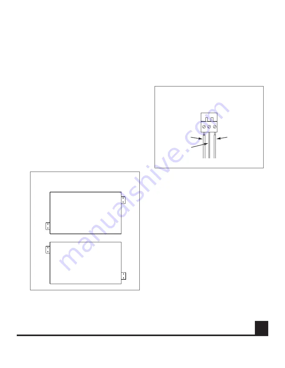
Locate the mounting holes on the left and right sides of
the unit, 2 sets of 2 horizontally aligned holes on each
side. Position the round screw-holes on the tabs over the
mounting holes on the 9900V, being sure that the oblong
screw-holes are flush with the bottom of the unit. Attach
each tab securely to the 9900V with 2 screws, but do not
over-tighten the screws. Refer to Figure 4.

Mount the 9900V to the wall, using 4 screws suitable for
fastening to the selected surface. Use screws that are suf-
ficiently long to provide secure mounting to the wall.

Power Connection

The 9900V series units are supplied with an external DC
power supply, model 648P. A permanently attached cable
is provided for the DC ouput and a detachable three-wire
grounded cable is provided for AC input.

CAUTION

:

Do not connect the unit to an AC power

source until directed to do so

.

1. Remove the detachable screw terminal power con-

nector from the back of the 9900V unit.

2. The external 648P power supply has a pendant  cable

with two tinned leads. Connect these leads to 
the power connector as shown in Figure 5.

3. Verify that the power supply is not connected to a wall

outlet, and insert the detached power connector into
its socket on the back of the 9900V unit.

See the Electrical Safety section on page 2 for additional
electrical connection information and safety precautions.

Do not plug the power supply into an AC outlet at this
time.

Fiber Optic Cable Connection

Most cable manufacturers identify the individual fibers in
the cable. Select appropriately terminated fiber and mark
both ends with unique identification label (e.g. for cable
no. 03, fiber no. 08) to ensure that the fiber connected to
the near end is the same one that is connected to the far
end.

The proper optical connection will link the transmitter's
OUT port to the receiver's IN port.

www.fiberoptions.com

[email protected]

free phone: 800.342.3748  

free fax: 877.342.3732

3

FIGURE 5: DETACHABLE SCREW TERMINAL

POWER CONNECTOR.

FIGURE 4: LOCATION OF BRACKETS FOR WALL 

MOUNTING.

To Power Supply

Black (-)

Red (+)

Chassis

Ground

Front

Rear

Rear

Front

or

continued on page 5

Summary of Contents for 9900V-T

Page 1: ... This manual is a guide to the installation and operation of the 9900V series fiber optic digital video transmission system and 9900VD series fiber optic digital video with return data transmission system Please read the entire manual before installing the equipment Note The series numbers 9900V T and 9900V R will be used to describe all models of transmitters and receivers unless noted otherwise ...

Page 2: ... radius limitation Also con sider future accessability issues when selecting the loca tion Refer to the included engineering drawings for front and rear panel layouts Rack mount Installation Using the 4 screws provided attach the rack mount tabs to the 9900V Locate the vertically aligned mounting holes on the left and right sides of the unit and position the round screw holes on the tabs over them...

Page 3: ...e supplied with an external DC power supply model 648P A permanently attached cable is provided for the DC ouput and a detachable three wire grounded cable is provided for AC input CAUTION Do not connect the unit to an AC power source until directed to do so 1 Remove the detachable screw terminal power con nector from the back of the 9900V unit 2 The external 648P power supply has a pendant cable ...

Page 4: ...nc Wire Color white orange black red green yellow blue violet Pin No Function 8 nc 7 nc 6 ground shield 5 nc 4 RS422 in 3 RS422 in 2 nc 1 nc Wire Color white orange black red green yellow blue violet Manchester Biphase Connection Manchester Biphase Connection Pin No Function 8 nc 7 nc 6 ground shield 5 nc 4 nc 3 nc 2 Manchester Biphase out 1 Manchester Biphase out Wire Color white orange black red...

Page 5: ...e RJ 45 plug which is then inserted into the corre sponding RJ 45 socket on the rear of the 9900VD unit Data connection must be made according to the tables on page 4 depending upon the data format being used Refer to Figure 6 Connection to the RJ 45 plug may also be made using a cable adapter which is provided with the 9900VD unit Refer to Figure 7 Table 2 Receiver LED Indicators Green or flashin...

Page 6: ...V1 T R 9914V1 T R 9904VD2L T R 9904VD2 T R 9904VD1 T R 9904V1L T R 9904V1 T R 9912V1 T R 9902VD2L T R 9902VD2 T R 9902VD1 T R 9902V1L T R 9902V1 T R 1 Fiber 1310 1550 nm 20 Channels 18 Channels 16 Channels 14 Channels 12 Channels 9920V1 R R 9918V1 R R 9916V1 R R 9914V1 R R 9912V1 R R 1 Fiber 1310 1550 nm 2 Fiber Data 1550 nm 2 Fiber Data 1310 nm 1 Fiber Data 1310 1550 nm 1 Fiber 1550 nm 1 Fiber 13...

Page 7: ... 3 RS485 out 2 RS485 out 1 Ground Shield Position B 2V offset Mode Switch SW1 RS485 4 Wire Interface Position A 1V offset Position 9 standard offset Pin No Function 8 Ground 7 nc 6 Manchester Biphase in 3 nc 5 Manchester Biphase in 4 nc 2 Manchester Biphase out 1 Manchester Biphase out Mode Switch SW1 Position 5 Manchester Biphase Interface Pin No Function 8 Ground 6 Manchester Biphase in 3 nc 5 M...

Page 8: ...60 86 54 53 Fax 33 01 60 86 86 04 Germany Tel 49 700 34237678 Fax 49 36256 21991 Hong Kong Tel 852 2907 8108 Fax 852 2142 5063 Latin America Tel 800 342 3748 Fax 877 342 3732 light years ahead FIGURE 1 ROTARY SWITCH SETTINGS TABLE 10 ROTARY SWITCH SETTINGS Setting Mode 0 Disable factory preset 1 RS232 3 wire 2 RS232 handshake 5 wire 3 TTL 4 RS422 5 Manchester Biphase 6 RS485 2 wire standard 7 RS48...

Reviews: