background image

data: 13/01/16

file: P1X_T_ing.doc

pag 10 di 11

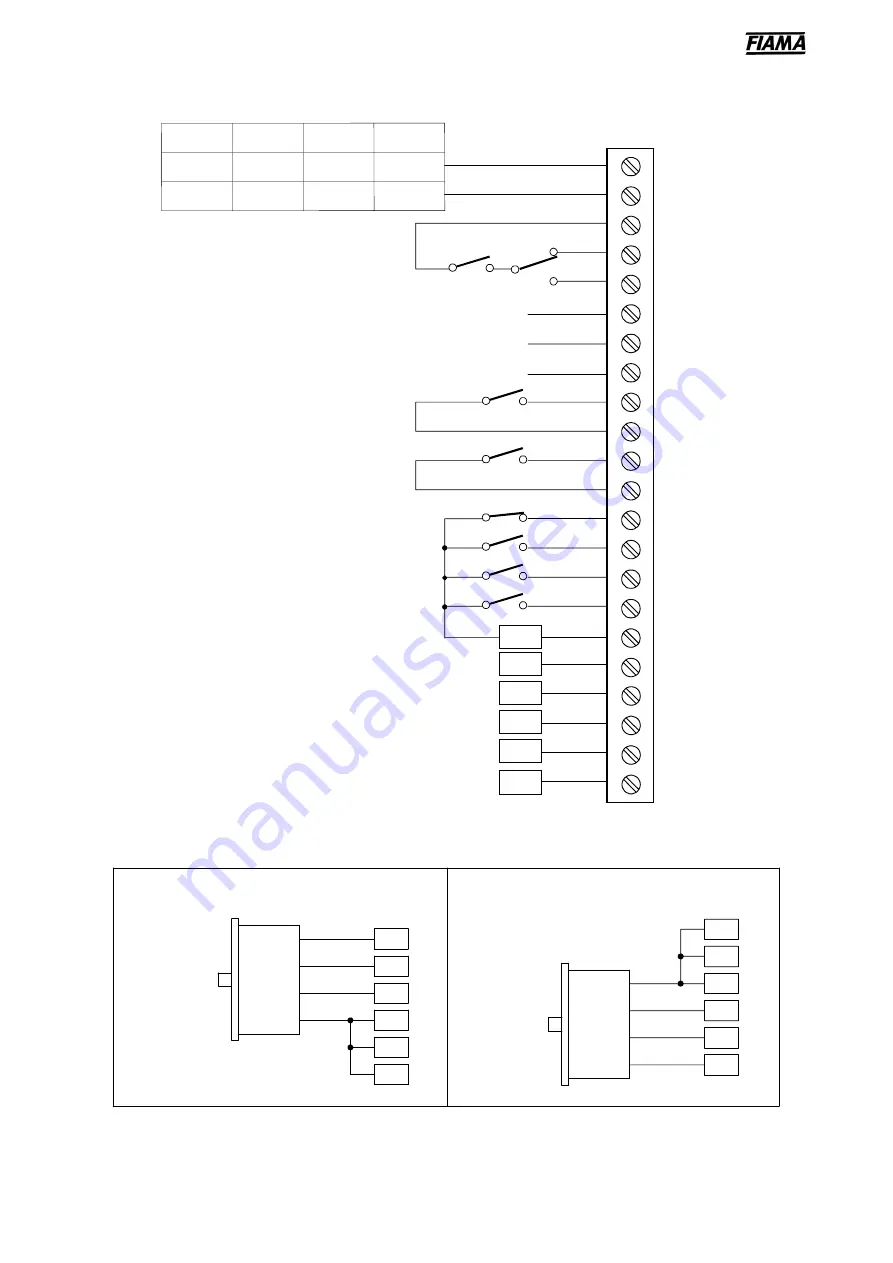
WIRING DIAGRAM

M1

BACKWARD

FORWARD

PIECES COUNTER input

17

18

1

2

3

4

5

6
7

8

9

10

11
12

13

14
15

16

19

20

21
22

START

END POSITIONING relay

EMERGENCY input

PRESET input

Transducer input

(see “


Transducer wiring diagram ”)

AUX OUTPUT relay

START/FORWARD/BACKWARD relais

GND

A

/A

B

/B

+12V

24 Vac

+24VDC

230 Vac

115 Vac

P1X2T

P1X3T

P1X1T

P1X0T

0

0

0

0

START input

analog output GND

analog output V+

analog output I+

Transducer wiring diagram

18

20

17

19

21

22

GND

A

B

+12V

/A

/B

GND

A

B

+Vcc

Connection bidirectional encoder open-
collector NPN or push-pull output

NPN

A

B

+12V

/A

/B

GND

GND

A

B

+Vcc

PNP

19

22

20

18

17

21

Connection bidirectional encoder open-
collector PNP or push-pull output

Summary of Contents for P1X0T

Page 1: ... 99 dimensions to create positioning programmes giving the possibility to manage for every dimension the number of parts that are to be processed in sequence as well as the number of cycle repetitions In order to optimize positioning accuracy there are some parameters that can counterbalance system inertia clearances and wear and tear of mechanical couplings Find below the other features character...

Page 2: ...up between 0 10V and 10 10V For the relevant connections see wiring diagram on page 10 Description of the front panel The display1 always displays the axis dimension whereas the other displays show different parameters as a function of the positioner status The function indicators show the currently selected function PROGRAMMING The keys used for programming are the following P Function choice pro...

Page 3: ...ith encoder zero notch or zero micro to zero set or preset the dimension Manual zero setting or presetting By pressing the E key or by enabling the PRESET input in the terminal box it is possible to zero set or to carry out a presetting of the dimension as a function of what was set in the constant on page 7 Automatic zero setting or presetting zero research By enabling the START input in the term...

Page 4: ...ber of memorised dimensions which must not exceed 99 for instance it is possible to create as ultimate limits either 99 programmes made by a single dimension or one single programme made by 99 dimensions The modification of the dimensions is protected by a password the password is requested through the display of letter P on display3 and of three zeroes the first one of them is blinking on display...

Page 5: ...ant is used for the applications that need cutting with material removal 2 PreStop The positioner stops the axis movement when it reaches the dimension amounting to the difference between the set dimension and the PreStop value This parameter enables to counterbalance the positioning inertia in systems with constant inertia It is advisable to enter the PreStop parameter after setting all the other...

Page 6: ...ging between 0 and 9999 milliseconds for all the motion reversing manoeuvres 11 Deviation dimension By setting this constant to a value differing from zero at the end of the positioning the instrument waits for the switchover from open to closed of the WORK COUNTER input to carry out an onward shifting of a dimension equal to the Deviation Dimension after that when a time equal to the Deviation Re...

Page 7: ...e 3 the zero setting presetting or zero research function Zero automatic research mode1 In the automatic zero setting function when the START key is pressed the slow backward motion of the axis is started searching for the zero input When the zero point is reached the axis motion continues for 2 seconds more and then stops and carries out the dimension presetting Zero automatic research mode 2 In ...

Page 8: ...it Don t set values that are upper then the Upper Limit for the values next constant or the positioner will not accept the start drives 25 Dimensions upper limit 0 0 0 0 As for the previous constant the positioner prevents the entry of dimensions exceeding the value set in this constant and interrupts the axis motion if during the positioning the dimension exceeds this limit Don t set the values t...

Page 9: ... the numerical keys indicated in the following figure the position of the hyphen indicates the output status to the hyphen in the high position low corresponds an enabled output not enabled START END POSITIONING FORWARD BACKWARD SLOW FAST DISPLAY2 START OUTPUT NONE AUX OUTPUT KEY TO BE PUSHED NONE 1 2 3 4 5 By pressing the E key it is possible to go back to the inputs test in order to leave the te...

Page 10: ...gram AUX OUTPUT relay START FORWARD BACKWARD relais GND A A B B 12V 24 Vac 24VDC 230 Vac 115 Vac P1X2T P1X3T P1X1T P1X0T 0 0 0 0 START input analog output GND analog output V analog output I Transducer wiring diagram 18 20 17 19 21 22 GND A B 12V A B GND A B Vcc Connection bidirectional encoder open collector NPN or push pull output NPN A B 12V A B GND GND A B Vcc PNP 19 22 20 18 17 21 Connection ...

Page 11: ...ic Absolute line Manual Single positioning Test Possibility to create working programmes 99 steps of program memory with the possibility of specifying the number of pieces and the number of cycle repeats Data storage with the machine switched off by EEPROM memory Extractable terminal junction box Input output test Relays output 250Vac 250Vac 10A resistive load Start forward backward Positioning en...

Reviews: