
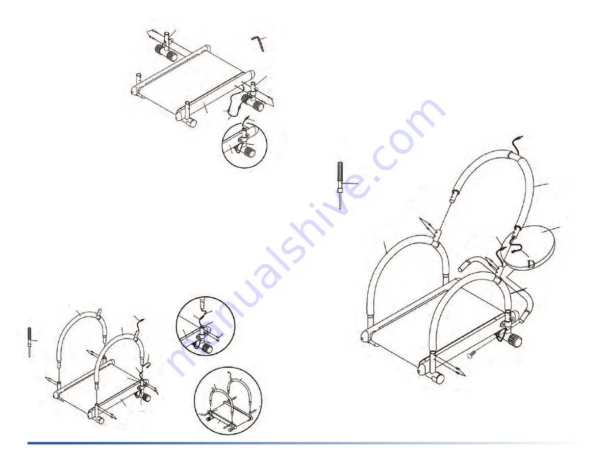
Step 3 / Étape 3
Connect Sensor Cable (A) with (D) before attaching the Front Handrail (11) to
Handrails (10a & b). Check the alignment of the screw holes, then fasten using
Long Screws (16). Attach the Twister Part (21) as shown. / Connecter le câble
du capteur (A) avec (D) avant de fixer la rampe avant (11) aux rampes droite et
gauche (10a et 10b). Vérifier l’alignement des trous de vis, puis fixer à l’aide
des vis longues (16). Fixer la partie “Twister” (21) tel qu’indiqué.
Figure 3
20
11
21
16
10b
10a
16
D
A
C
B
A
18
1
9
16
16
16
16
10a
10b
20
Step 2 / Étape 2
Slide the Sensor Cable (C-Fig. 2a) to the slot on the Plastic Cap (18). Press into
the hole on the Right Leg Tube (9), as shown. Pull the exposed part of the Sensor
Cable from the top, until it is tight. Connect the Cable (C) and (B) together with
Cap (18) before inserting the Right Handrail (10a) to the Frame and Leg Tube (9).
Connect the Left Handrail (10b) as shown. Tighten with Screws (16). / Faites
glisser le câble du capteur (C- fig . 2a) par la fente sur le capuchon en plastique
(18). Insérer dans le trou du tube de jambe droite (9), tel qu’indiqué. Tirer sur
la partie exposée du câble du capteur par le haut, jusqu’à ce qu’il soit serré.
Brancher le câble (C) et (B) avec le capuchon (18) avant d’insérer la rampe droite
(10a) au cadre et au tube de jambe droite (9). Connecter la rampe gauche (10b)
tel qu’indiqué. Serrer avec les vis.
Figure 1
Figure 1a
19
8
9
15
1
1
15
18
C
C
18
Figure 2
C
B
18
1
9
16
16
16
16
10b
A
10a
8
1
16
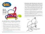
Step 1 / Étape 1
Attach Left (8) and Right Leg
Tube (9) to Frame (1) with Bolts
(15). Guide the Sensor Cable
(C) through the hole in Right
Leg Tube (9) as shown. / Fixer
le tube de jambe gauche (8)
et le tube de jambe droite (9)
au cadre principal (1) avec des
boulons (15). Passer le câble
du capteur (C) dans l’orifice du
tube de la jambe droite (9) tel
qu’indiqué.
Figure 2b
Figure 2a