
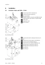
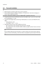


3. Connect TTL input of the sensor interface CASB-MT-D3-R7 and the RJ-45 input of the safety relay
unit with the connecting cable NEBU-M12W8-K-5-N-LE8.
–
If required, use the enclosed RJ-45 plug.
–
When using clamping or cutting connections: cut the tin-plated ends of the connecting cable
NEBU-M12W8-K-5-N-LE8.
4. Connect the HTL input of the sensor interface CASB-MT-D3-R7 and the corresponding inputs of the
safety relay unit with the connecting cable NEBU-M12G5-K-5-LE4.
5. Connect the sensor interface CASB-MT-D3-R7 and valve unit VPCB with the connecting
cable KM12-8GD8GS-2-PU.
6. Connect the shut-off valves of the valve unit VPCB and the corresponding inputs of the safety
relay unit with the connecting cables KME-1-24DC-5-LED.
7. Assemble the plug NECC-S1G9-C2-M in accordance with the enclosed circuit diagram YHBP.
Observe accompanying installation instructions for the plug NECC-S1G9-C2-M
è
8. Switch on integrated 120 Ω bus termination in the plug NECC-S1G9-C2-M.
9. Connect the CAN interface [X1] of the balancer controller CECC-D-BA with the corresponding input
of the valve unit VPCB.
–
Install cable without tension.
10. Create the remaining connections to the balancer controller CECC-D-BA in accordance with the
application.
11. Create the remaining connections to the safety relay unit in accordance with the application.
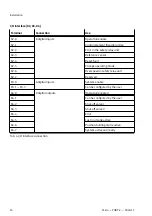
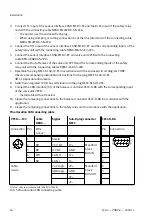
Pin allocation CAN connecting cable
VPCB-...-T22
Cable
NEBC-...
Signal
Sub-D plug connector
NECC
CECC-D-BA
Connection Pin
Wire
colour
1)
Pin
Connection
1
–
Shield
–
–
–
2
RD
24 V DC
1V+
–
3
BK
0 V DC
GND
3
4
WH
CAN_H
1C+
7
5
BU
CAN_L
1C
–
Manifold
block
BUS IN
2
24 V logic
2V+
9
GND logic
GND
3
–
2C+
–
Cable,
2-wire
–
2C
–
Manifold
block
BUS OUT
–
1) Colour code in accordance with IEC 60575:1983-01
Tab. 5 Pin allocation CAN connecting cable
Installation
16
Festo — YHBP-2 — 2018-11


