background image

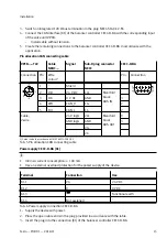
Power supply of the digital I/Os [X5]

Resultant current for all supplied ports: 

£

 2 A

Terminal

Connection

Use

X5.1

24

24 V DC

X5.2

0

0 V DC

Tab. 7 Connection, power supply for digital I/Os

1. Supply the device with power.
2. Place the open cable ends in the plug provided in accordance with the table.
3. Insert the plug into the connection [X5] of the controller.

Connection, reference sensor

Connect the proximity sensor SMT-8M-A-PS-24V-...-OE that serves as a reference sensor as follows.

SMT-8M-A-PS-24V-...-OE

CECC-D-BA

Wire colour

1)

Function

Connection

BN

24 V DC supply

24 V load

BK

Switching output

Digital input X2.3

BU

GND

24 V GND

1) Colour code in accordance with IEC 60575:1983-01

Tab. 8 Connection, reference sensor

Earthing

Connect the earth terminal of the mono-block valve unit VPCB using an earthing cable, self-tap-
ping screw and toothed disc (included in the scope of delivery) with low impedance to the earth
potential.

Connect the earth terminal of the sensor interface CASB-MT-D3-R7 with low impedance to the
earth potential.

Installation

16

Festo — YHBP-1 — 2018-11

Summary of Contents for YHBP-1

Page 1: ...8088702 YHBP 1 Balancer kit 8088702 2018 11 8088704 Instructions Assembly Installation...

Page 2: ...Translation of the original instructions 2 Festo YHBP 1 2018 11...

Page 3: ...4 Service 6 5 Product overview YHBP 7 5 1 Scope of delivery 7 5 2 Function 8 6 Transport 8 7 Assembly 9 8 Installation 10 8 1 Interfaces of valve unit VPCB T22 10 8 2 Pneumatic installation 11 8 3 In...

Page 4: ...Instruction manu al Control element VAOH P15 H13 Operation Instruction manu al Valve unit VPCB T22 Operation installation Instruction manu al Connector SET VABS P15 S B6 Assembly Description Controlle...

Page 5: ...ey Data Matrix Code of the product 2 Download documents from the Festo Support Portal by entering the order ID product key Data Matrix Code www festo com sp 3 Print out documents and keep together wit...

Page 6: ...d and the manufacturer is not liable for damages 2 3 Foreseeable misuse Never use the product as follows With unauthorised modifications or alterations to the product With load limits exceeded In an i...

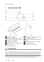
Page 7: ...rol element VAOH 11 Tubing not in scope of delivery Fig 1 Product overview YHBP 5 1 Scope of delivery The kit only contains individual components that can be used for building a servo pneumatic balanc...

Page 8: ...escription of the operating modes can be found in the application notes 1 1 Applicable documents 6 Transport Sequence of transport and unpackaging NOTICE Damage to the product due to incorrect transpo...

Page 9: ...Applicable documents Attach the proximity sensor near the lower end position of the DNCI Tightening torque 0 6 Nm 3 Assemble the displacement encoder DNCI backlash free and parallel to the cylinder DS...

Page 10: ...r direct pressure measurement on cylinder DSBG 6 Status LED 7 Power Error LED 8 Earth connection Fig 2 VPCB interfaces 2 Connection 2 G3 8 for working air balancer cylin der 9 Connection G1 8 for pneu...

Page 11: ...ter 12 mm 2 Connect pressure gauge input connection 9 Bedienelement of valve unit VPCB with handle VAOH Tubing diameter 6 mm Tube length 0 5 m 10 m 3 Assemble the silencer not in scope of delivery as...

Page 12: ...O interfaces X2 X3 X4 X5 6 CAN interface X6 7 Power supply for the I O interfaces X5 Fig 4 Interfaces CECC D BA The status LEDs show the operating status of the CECC D BA Status LED Meaning Run Applic...

Page 13: ...mode X2 6 Reserved X2 7 Reserved X3 0 6 digital inputs System enable X3 1 X3 5 Can be configured by the user X4 0 8 digital outputs Operation enabled X4 1 Can be configured by the user X4 2 Shut off v...

Page 14: ...ava Script and support of HTML5 Canvas e g Firefox Chrome Internet Explorer Version 9 Screen resolution 1280 x 768 pixels 8 4 Electrical installation WARNING Risk of injury due to electric shock For t...

Page 15: ...4 WH CAN_H 1C 7 5 BU CAN_L 1C Manifold block BUS IN 2 24 V logic 2V 9 GND logic GND 3 2C Cable 2 wire 2C Manifold block BUS OUT 1 Colour code in accordance with IEC 60575 1983 01 Tab 5 Pin allocation...

Page 16: ...that serves as a reference sensor as follows SMT 8M A PS 24V OE CECC D BA Wire colour1 Function Connection BN 24 V DC supply 24 V load BK Switching output Digital input X2 3 BU GND 24 V GND 1 Colour c...

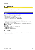
Page 17: ...sis must be carried out and all appropriate measures implemen ted Commissioning is dependent on the customer specific application During commissioning observe the associated documentation for the indi...

Page 18: ...unctions The display and elimination of malfunctions are dependent on the customer specific application During operation observe the associated documentation for the individual components installed 1...

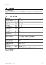
Page 19: ...80 200 Travel speed m s 1 Operating voltage DC V 21 6 26 4 Duty cycle 100 Residual ripple 5 Operating pressure bar 4 8 Operating medium Compressed air to ISO 8573 1 2010 6 4 4 Lubricated operation no...

Page 20: ...ization is prohibited Offenders will be liable for damages All rights reserved in the event that a patent utility model or design patent is registered Copyright Festo AG Co KG 73734 Esslingen Ruiter S...

Reviews:

Related manuals for YHBP-1