


4.2 Electrical
Note
The degree of protection IP67 depends on the type of electrical connection.
Inappropriate cables or incorrect installation reduce the degree of protection of
the sensor box.
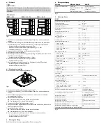
Terminal diagram
SRBC-...-1W
SRBC-...-ZC/-ZU
SRBC-...-N/-P
Solenoid Valve
Solenoid Valve
Solenoid Valve
Solenoid Valve
+
+
–
–
+
+
–
–
Fig. 3
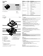
1. Loosen the housing screws
3
on the housing cover. Remove the housing cover.
2. Screw the cable connector into the cable entry. Guide the electric connecting
cable through the cable connector to the terminal block.
– cable connector tightening torque 4.5 Nm.
– outside diameter of electric connecting cable: 5…13 mm.
– conductor cross section: 0.25 ... 2.5 mm
2
.
3. Seal unused cable entries with blanking plugs.
4. Wire connections (
è
Fig. 3).
5. Connect the earth terminal with low impedance (short cable with large cross
section) to the earth potential.
– earth terminal tightening torque: 1. 3 Nm.
6. Tighten the union nut on the cable connector.
– Tightening torque 4 Nm.
7. Put on the housing cover and tighten the 4 housing screws
3
.
– Make sure that the seal is positioned correctly
– tightening torque 2 Nm ± 10 %.
4.3 Set switching points
The switching points are preset (
è
Chap. 1).
Fig. 4
1. Close process valve. Position indicator: “closed”.
2. Loosen the housing screws
3
on the housing cover. Remove the housing cover.
3. Lift the red cam against the spring and turn until the lower proximity sensor
switches.
4. Release the red cam.
è
The spring presses the red cam into the ring gear.
è
The switching point for “closed” is set.
5. Open process valve. Position indicator: “open”.
6. Press down the green cam against the spring and turn until the upper proximity
sensor switches.
7. Release the green cam.
è
The spring presses the green cam into the ring gear.
è
The switching point for “open” is set.
8. Put on the housing cover and tighten the 4 housing screws.
– Make sure that the seal is positioned correctly
– Tightening torque 2 Nm ± 10 %.
5
Maintenance and care
If used as intended, the product is maintenance-free.
6
Fault clearance
Malfunction
Possible cause
Remedy
Incorrect or unexpected signal
Wire break
Replace cable
Position of the switching
points incorrectly defined
Set switching points
(
è
Chap. 4.3)
Proximity sensor defective
Replace sensor box
Fig. 5
7
Technical data
SRBC
Setting range for angle acquisition
[°]
0 … 90
Cable connector
M20x1.5
Permissible cable diameter
[mm]
5 … 13
Electrical connection
10-pin, screw terminal
Connectable nominal conductor cross section
[mm²]
0.25 ... 2.5
Mounting position
Any
Operating voltage range AC
– SRBC-...-2A
[V]
0 … 120
– SRBC-...-22A
[V]
0 … 250
Max. output current AC
– SRBC-...-2A
[mA]
250 (at 120 V)
– SRBC-...-22A
[mA]
3000 (at 250 V)
Operating voltage range DC
– SRBC-...-2A-1W
[V]
0 … 175
– SRBC-...-22A-1W
[V]
0 … 30
– SRBC-...-20N-ZC
[V]
8.2
– SRBC-...-1-P / SRBC-...-1-N
[V]
10 … 30
– SRBC-...-1-ZU
[V]
5 … 60
Max. output current DC
– SRBC-...-2A-1W
[mA]
250 (at 175 V)
– SRBC-...-22A-1W
[mA]
3000 (at 30 V)
– SRBC-...-20N-ZC
[mA]
3
– SRBC-...-1-P / SRBC-...-1-N / SRBC-...-1-ZU
[mA]
100
Voltage drop
– SRBC-...-1-P / SRBC-...-1-N
[V]
3
– SRBC-...-1-ZU
[V]
5
Residual current
– SRBC-...-P / SRBC-...-N
[mA]
15
Idle current
– SRBC-...-P / SRBC-...-N
[mA]
0 … 0.5
– SRBC-...-1-ZU
[mA]
0 … 1
Reverse polarity protection
– SRBC-...-P / SRBC-...-P / SRBC-...-ZU
For all electrical connections
Protection against short circuit
– SRBC-...-P / SRBC-...-N
Clocked
Ambient temperature
– SRBC-...-1-P / SRBC-...-1-N /
SRBC-...-20N-ZC-...-EX4
[°C]
-20…70
– SRBC-...-2A-1W / SRBC-...-22A-1W /
SRBC-...-20N-ZC / SRBC-...-1-ZU
[°C]
-20…80
Degree of protection
IP67, NEMA 4/4X
Continuous shock resistance in accordance with
DIN/IEC 68, Part 2-82
±15 g with 6 ms duration;
1000 shocks per direction
Vibration resistance in accordance with DIN/IEC 68,
Part 2-6
0.35 mm travel at 0 ... 60 Hz;
5 g acceleration at 0 ... 150 Hz
Information on materials, housing
Painted die-cast aluminium
Information on materials, shaft
High-alloy stainless steel
Information on materials, seal
NBR
Information on materials, screws
High-alloy stainless steel
Information on materials, visual position indicator
PC
Information on materials, mounting adapter
High-alloy stainless steel
Information on materials, cable connector / blanking plug
PA
CE marking (see declaration of conformity
è
www.festo.com)
Fig. 6


