


The LRP-1/8-6 can be fastened in one of three ways:
– front panel mounting (diameter for the cutout: 32 ±0.1 mm),
– line fitting using the piping,
– with accessories (fastening bracket
aJ
).
When mounting the front panel and for installation with mounting bracket:
1. Unscrew the knurled nut
9
.
2. Push the regulator head through the cutout in the front panel or through the
ring bore of the mounting bracket
aJ
.
3. Tighten the knurled nut
9
without any aids.
When mounting the precision pressure gauge:
1. Remove the blanking screw
3
.
2. Screw the precision pressure gauge
2
into the LRP in a clockwise direction as
far as possible (tightening torque: max. 7 Nm). The spanner flat must be hori-
zontal.
When removing the precision pressure gauge:
1. Unscrew the precision pressure gauge
2
out of the LRP in anti-clockwise direc-
tion.
2. Screw the blanking screw
3
into the LRP (tightening torque: 1.5… 1.8 Nm).
LRP-7.0-6
• Ensure that the sealing rings
aD
are correctly seated.
The LRP-7.0-6 can only be fixed to the connection block
aE
:
1. Lubricate the sealing rings
aD
lightly and position them on the pneumatic con-
nections of the LRP.
2. Position the LRP on the connection block
aE
. The sealing rings
aD
may not fall
out of their position.
3. Mount the LRP on the connection block
aE
using two screws
aA
(tightening
torque: 2 Nm).
4.2 Pneumatic
Note
Fittings with an excessively long screw-in length or sealing tape can cover trans-
verse bores in the connecting thread of the LRP and thereby impair reliable func-
tioning.
• Use appropriate fittings with a max. length of 8 mm.
• Do not use sealing tape or sealing material (e.g. Loctite) to seal the fittings.
• Screw the connectors into the pneumatic ports.
5
Commissioning
Warning
If port 2 is not connected, the inlet pressure will be at maximum height due to
lack of feedback.
• Make sure that exhaust air is not passed into the environment through port 2.
• Connect a consumer to port 2.
When setting the precision pressure regulator type LRP:
1. Pull the rotary knob up and away from the housing.
The rotary knob is in the regulating position.
2. Turn the rotary knob completely closed in the “–” direction.
3. Supply the system with air slowly.
4. Turn the rotary knob in the “+” direction until the desired pressure is displayed
on the precision pressure gauge.
The permissible pressure regulation range (
10 Technical data) must not be
exceeded. Correctly pressurised, the inlet pressure p1 is at least 0.5 bar higher
than the outlet pressure p2.
5. Press the rotary knob down to the housing.
The rotary knob will then lock itself against unintentional turning.
6
Operation
Note
For design reasons, the device has slightly audible internal air consumption
(
10 Technical data).
• Note the control precision of the LRP during operation.
If the LRP deviates to above the tolerance limit:
• Remove any contamination from the inside (
7 Maintenance and care).
7
Maintenance and care
• If necessary, clean the LRP on the outside with a soft cloth.
A permissible cleaning agent is soap suds (max. +60 °C).
If the interior is dirty
Replacing the filter flow control screw:
1. Exhaust the LRP.
2. Loosen the filter flow control screw
8
by turning it in an anti-clockwise direc-
tion.
3. Lubricate the sealing ring of the new filter flow control screw lightly.
4. Screw the filter flow control screw
8
back into the LRP in a clockwise direction
(tightening torque: 0.4 ±0.1 Nm).
The filter flow control screw will grip the sealing ring only when it is screwed in
with a certain amount of force.
Cleaning the valve seat:
1. Exhaust the LRP.
2. Carefully remove the cover
4
by turning it with a screwdriver in an anti-clock-
wise direction.
The valve spring
5
and the valve stem
6
will then be lifted out at the same
time.
3. Clean the valve seat on the valve stem
6
with a soft cloth.
A permissible cleaning agent is soap suds (max. +60 °C).
4. Lubricate slightly the valve seat and the sealing ring on the cover.
5. Screw the cover
4
together with the valve spring
5
and the valve stem
6
into
the LRP (tightening torque: 2.2 ±0.4 Nm).
6. Perform recommissioning of the LRP in accordance with the chapter
Commissioning.
8
Accessories
Designation
Type
Lubricating grease
LUB-KB2 (on request)
Fig. 3
9
Fault clearance
Malfunction
Possible cause
Remedy
Audible air flow through the
cover.
Internal air consumption
No malfunction
Deviations of control precision
outside the tolerance limit.
Filter flow control dirty
• Replace the filter flow control
(
7 Maintenance and care).
Still a high degree of exhaust
air at the exhaust port.
Valve seat dirty
• Clean and grease the valve seat
(
7 Maintenance and care).
Input pressure is at full height
at output p2.
Non-permitted blowing out
at pressure output
• Connect the current-consum-
ing device (p2 ≠ 0 bar).
Fig. 4
10
Technical data
LRP-…
x
-6
7.0-6
Inlet pressure
[bar]
1 … 8
Pressure regulation range
1)
[bar]
0.1 … 6
Operating medium
Filtered, unlubricated compressed air, grade of filtration 40 μm
Mounting position
Any
Ambient temperature
[°C]
–10 … +60
Temperature of medium
[°C]
–10 … +60
1)
If the difference in pressure between the inlet pressure and outlet pressure falls below 2 bar, a fluctu-
ation of max. ±0.01 bar in the outlet pressure is possible.
Fig. 5
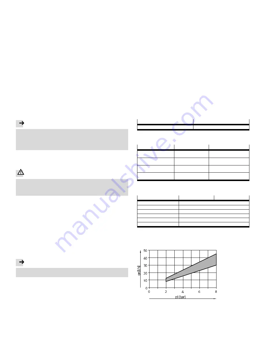
Internal air consumption qn as a function of the inlet pressure p1:
Fig. 6


