


Damage to the device due to non-approved potentials at the pins
• Power connection:
• Do not connect pin 3
• Logic connection:
• Only after connection of the reference potentials GND/L– [Pin 4/8] can 24V
levels be applied to digital outputs DO1/DO2 [Pin 2/3] or the IO-Link
communication signal C/Q [Pin 3].
• The digital outputs DO1/DO2 [Pin 2/3] and the IO-Link communication
signal C/Q [Pin 3] must be disconnected 100 ms before the power
supply connections GND/L– [Pin 4/8] and 24 V DC/L + [Pin 1], e.g. by
the interposition of relay contacts.
1. Connect the cables to the [Logic] and [Power] connections of the integrated
drive EMCS-ST.
2. Connect cables to the controller or IO-Link master and to the PELV fixed power
supply units.
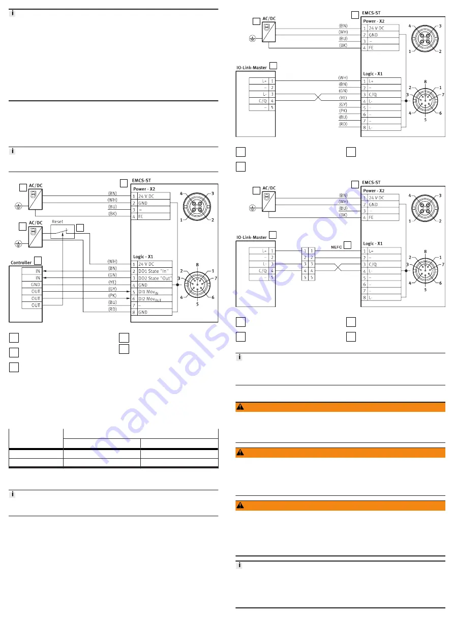
Wiring diagram: DIO operation (digital I/O)
In NPN mode defined levels must be applied to the digital inputs DI1/DI2 of the
EMCS, e.g. by controller outputs with pull-up resistors (4.3 k
W
recommended).
1
2
3
4
5
Fig. 5: Wiring diagram: DIO operation (digital I/O)
1
PELV fixed power supply for load
voltage supply
2
PELV fixed power supply for logic
power supply
3
Reset button for acknowledging
an error and triggering a restart
(optional)
4
Integrated drive EMCS-ST
5
Higher-level controller with dig-
ital I/O
Status and control signals
The following table shows the status and control signals and the electrical levels
of the digital inputs and outputs as a function of the "PNP/NPN" version of the
integrated drive. The following timing diagrams only show the status and control
signals of the PNP version.
Status and control
signal
Electrical levels
PNP, positive logic
NPN, negative logic
0
Low level (0 V)
High level (24 V)
1
High level (24 V)
Low level (0 V)
Tab. 2: Overview of status and control signals as a function of electrical levels
Wiring diagram: IO-Link operation, port class A (with and without NEFC adapter)
Current consumption of IO-Link power supply [Logic]
An input current at pin 1 (L+) of 100 ... 150 mA is required for operation.
1
2
3
Fig. 6: Wiring diagram: IO-Link operation
1
PELV fixed power supply for the
load voltage supply
2
Integrated drive EMCS-ST
3
IO-Link master with IO-Link inter-
face
1
2
3
4
Fig. 7: Wiring diagram: IO-Link operation with adapter
1
PELV fixed power supply for load
voltage supply
2
Integrated drive EMCS-ST
3
IO-Link master with IO-Link inter-
face
4
Adapter NEFC
Core colours of Festo cables:
BK = black, BN = brown, BU = blue, GN = green, GY = grey, PK = pink,
WH = white, YE = yellow
8
Commissioning
WARNING
Risk of injury due to unexpected movement of components.
• Protect the positioning range from unwanted intervention.
• Keep foreign objects out of the positioning range.
• Perform commissioning with low dynamic response.
WARNING
Severe, irreversible injuries from accidental movements of the connected
actuator technology.
Unintentional movements of the connected actuator technology can result from
exchanging the connecting cables of a servo drive or between servo drives.
• Before commissioning: All cables must be correctly assigned and connected.
WARNING
Danger of burns from hot housing surfaces.
Metallic housing parts can reach high temperatures during operation.
Contact with metal housing parts can cause burn injuries.
• Do not touch metallic housing parts.
• After the power supply is switched off, let the device cool down to room
temperature.
Update device data (only via IO-Link)
• Update firmware
• Update parameter set
• Data backup (Data Storage)
è
"Integrated drive EMCS" instruction manual
8.1
Commissioning: DIO operation (digital I/Os)
Preparation:


