Festo ELCC-TB Operating Instructions Manual Download Page 7

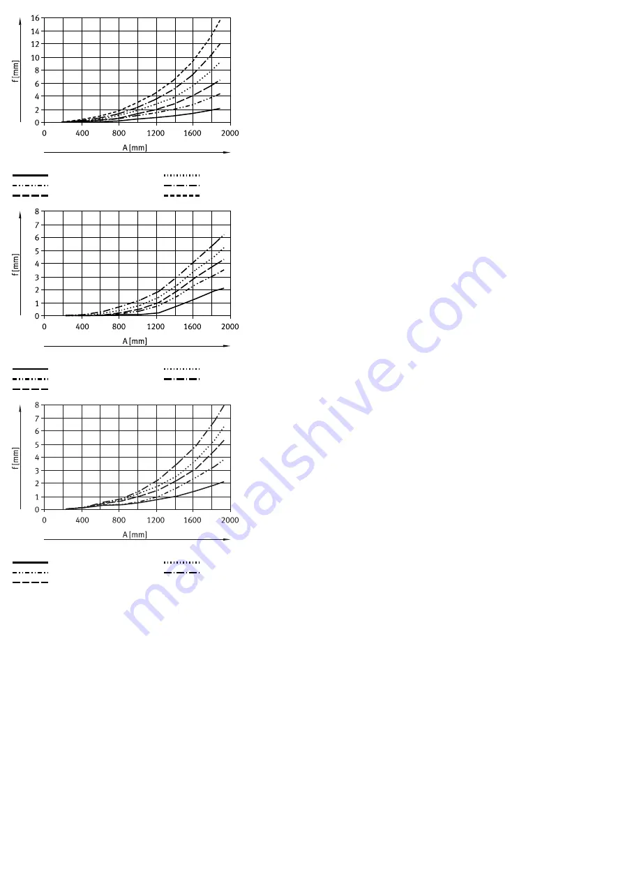
Fig. 12: ELCC-TB-90, vertical

 m = 0 kg
 m = 10 kg
 m = 20 kg

 m = 30 kg
 m = 40 kg
 m = 50 kg

Fig. 13: ELCC-TB-110, horizontal

 m = 0 kg
 m = 20 kg
 m = 30 kg

 m = 40 kg
 m = 50 kg

Fig. 14: ELCC-TB-110, vertical

 m = 0 kg
 m = 20 kg
 m = 30 kg

 m = 40 kg
 m = 50 kg

Summary of Contents for ELCC-TB

Page 1: ...l or for emergency braking in the event of a power failure Sensors and displacement encoder enable query of end positions refer ence position and intermediate position 4 2 Product design Product desig...

Page 2: ...screw in depth Tab 5 Requirement for attachment component Requirement No collision in the movement space of the attachment component with motor mounting and sensor components Flatness t of the mounti...

Page 3: ...ark Running noises during operation Identically constructed axes can generate different running noises depending on the parameterisation mode of operation type of mounting installation environ ment an...

Page 4: ...pull the housing 2 off the drive head 9 4 Lubrication Lubrication interval and accessories NOTICE The lubrication interval Sint is dependent on the load acting on the product Load factors include e g...

Page 5: ...cal Festo Service Replace axis www festo com catalogue Holding force is not reached Clamping component worn or clamping mechanism defective Contact local Festo Service Replace axis www festo com catal...

Page 6: ...e Weight Basic weight at 0 mm stroke kg 4 15 7 96 15 71 27 30 Added weight per 10 mm stroke kg 0 038 0 063 0 097 0 148 Weight of additional slide ELCC TB ZR ZL kg 1 91 4 32 6 72 11 71 Weight of clampi...

Page 7: ...2 ELCC TB 90 vertical m 0 kg m 10 kg m 20 kg m 30 kg m 40 kg m 50 kg Fig 13 ELCC TB 110 horizontal m 0 kg m 20 kg m 30 kg m 40 kg m 50 kg Fig 14 ELCC TB 110 vertical m 0 kg m 20 kg m 30 kg m 40 kg m 5...

Reviews: