


Requirement
–
Only loosen screws or threaded pins that are described in the directions in the
instruction manuals.
–
Sufficient space for reaching and securing the sealing air connection
1. Select the motor and motor mounting kit from
Festo
If other motors are used: observe the critical limits for forces, torques and
velocities.
2. Fasten motor mounting kit, observe instruction manual
3. Fasten the motor without tension. Support large and heavy motors.
Connect motor cables only on completion of mounting.
6.4
Mounting mini slide
Requirement
–
No collision in the range of motion of the attachment component with motor,
mounting components and sensor components.
–
Sufficient space for reaching and securing the sealing air connection.
–
Flatness of the mounting surface of 0.05% of the stroke length or maximum
0.2 mm over the stroke length of the bearing surface.
–
No distortion or bending when installing the product.
1. Select mounting attachments
2. Direct fastening: remove rubber cover caps from centring holes or threaded
holes.
3. Direct fastening: place centring components in the centring holes.
Profile mounting: place mounting attachments on the support points.
4. Tighten retaining screws.
Observe the maximum tightening torque and screw-in depth.
For additional information, contact your local Festo Service.
Direct mounting
Profile mounting EAHF-L2
Mounting via thread
Mounting via profile groove
Tab. 2: Overview of mounting components
Size
25
32
45
60
Direct mounting
Screw
M3
M4
M5
M5
Max. screw-in depth t
max
[mm]
6
8.5
7
8
Max. tightening torque
[Nm]
1.4
3.2
3
3
Centring hole and centring element,
centre
[mm]
Æ
2
Æ
4
Æ
5
Æ
7
Centring hole and centring element, out-
side
[mm]
Æ
5
Æ
7
Æ
7
Æ
7
Centre hole tolerance
H7
Profile mounting EAHF-L2
Screw
Instruction manual
Tab. 3: Information for mounting components
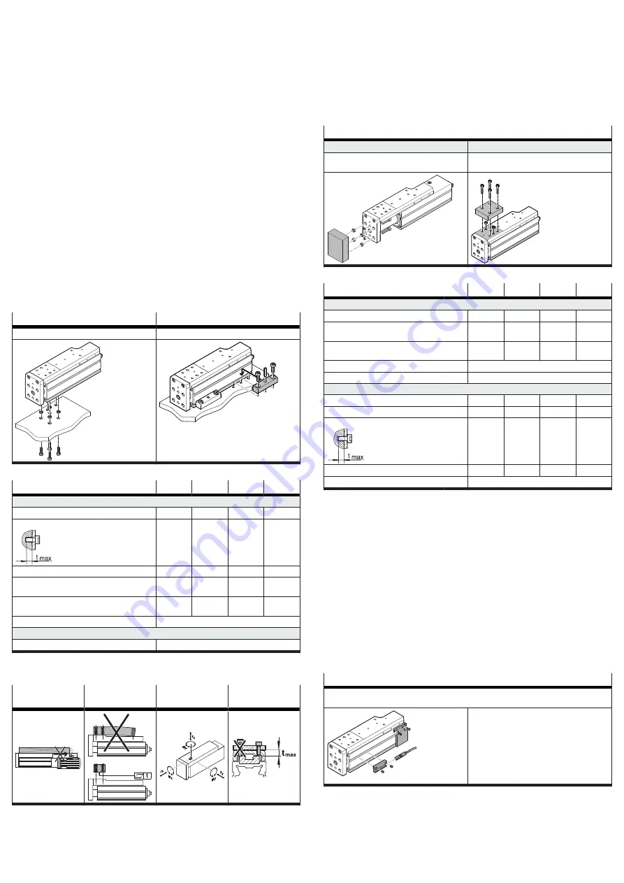
6.5
Mounting the attachment component
Collision-free
Flatness
Guide load
Max. screw-in
depth
Tab. 4: Requirement for attachment components
Requirement:
–
No collision in the range of motion of the attachment component with motor,
mounting components and sensor components.
–
Flatness of the mounting surface of the attachment component of 0.01 mm
above the slide surface.
–
Minimise guide load. Short lever arms from the guide centre
to the force
application points and centres of gravity of the add-on elements.
1. Select accessories
2. Place centring components in centring holes.
3. Position the attachment component on the slide or yoke plate.
4. Tighten retaining screws.
Observe the maximum tightening torque and screw-in depth.
Direct mounting
Yoke plate
Slide
Mounting via through-hole
Mounting via thread (only mount on marked sur-
face)
Tab. 5: Overview of attachment components
Size
25
32
45
60
Direct fastening of yoke plate
Screw
M3
M4
M5
M5
Centring hole and centring element,
centre
[mm]
Æ
2
Æ
4
Æ
5
Æ
7
Centring hole and centring element, out-
side
[mm]
Æ
5
Æ
7
Æ
7
Æ
7
Centre hole tolerance, centre
H8
Centre hole tolerance, outside
H7
Direct fastening on slide
Screw
M3
M4
M5
M5
Max. tightening torque
[Nm]
1.5
2.7
5.1
6.5
Max. screw-in depth t
max
[mm]
4.5
5
6
8
Centring hole and centring element
[mm]
Æ
2
Æ
4
Æ
5
Æ
7
Centre hole tolerance
H7
Tab. 6: Information on attachment components
6.6
Mounting accessories
Requirement
–
No collision in the range of motion of the attachment component with motor,
mounting components and sensor components.
Function
–
Protection against uncontrolled overtravel of the end positions.
–
Referencing to reference switch or end position.
–
Query of end positions or intermediate positions.
–
Prevention of hard impacts at the end positions.
–
Prevention of contamination in the slots.
1. Select accessories
2. Mount sensor for reference or query:
–
Mount sensor bracket and switch lug.
–
Align sensor and mount it at the switching position.
–
Fasten cable.
Sensor bracket EAPM and switch lug EAPM
–
Switch lug: mounting on slide
–
Sensor bracket: mounting via profile groove
–
Protect the sensor from external magnetic or
ferritic influences, e.g. min. 10 mm distance
to slot nuts.
–
Preferably use hardware limit switches with
N/C contact function to ensure protection in
the event of a sensor failure.
–
Query switching lug only with inductive
sensor.
Tab. 7: Overview of sensor mountings


