7
Operation
Warning
Danger of crushing! Danger of shearing!
The piston rod moves fast and with great force. Body parts in the movement
range of the piston can be crushed or severed.
Do not reach into the movement range of the piston rod.
Do not place foreign objects in the movement range of the piston rod.
Observe the operating conditions.
Observe permitted limit values.
8
Maintenance and care
If used as intended, the product is maintenance-free.
9
Disassembly
Note
Disassembly only by qualified specialized personnel.
1. Disconnect the drive from the power supply (operating medium, electric power).
2. Loosen the mounting screws ( Fig. 5,
1
) and carefully remove the housing.
3. Disconnect electrical and pneumatic connection.
4. Loosen the mounting screws and remove the drive.
Loosening a hose
1. Press down on the disconnect ring (blue) of the push-in fitting and hold it down.
2. Carefully pull the tube out of the push-in fitting.
Cut off the damaged part before using the hose further.
10
Disposal
Observe the local specifications for environmentally friendly disposal.
Dispose of the product in an environmentally friendly manner. When doing this,
also take residual media into account (potential recycling of hazardous waste).
11
Fault clearance
Malfunction
Possible cause
Remedy
Piston rod does
not move in the
desired direction
Displacement encoder cable incorrectly connected
at positioning controller or DFPI
(e.g. connections at pin 1 and pin 3 interchanged).
Correct the connection
Supply ports connected incorrectly
Correct the connection
Fig. 8
12
Technical data
DFPI-…
-100
-125
-160
-200
-250
-320
Type of mounting
Mounting interface in accordance with ISO 15552
Spanner size of the piston rod
22
27
36
36
46
55
Stroke
[mm]
40 … 990
Min./max. stroke allowance
[mm]
0 … 4
Design
Piston rod, cylinder barrel
Cushioning
No cushioning
Mounting position
Any
Mode of operation
Double-acting
Position sensing
Via integrated displacement encoder
Measuring principle of displacement enco
der
Potentiometer
Operating voltage range
[V DC]
0 … 15
Independent linearity
[%
FS]
±0.04
Hysteresis
[mm]
0.33
Repetition accuracy
[mm]
±0.12
Resistance value of displacement encoder (on the T.E.P.) dependent on the stroke length
1)
–
š
290 mm
[kΩ]
5
–
,
290 mm to 590 mm
[kΩ]
10
–
,
590 mm to 990 mm
[kΩ]
20
Recommended current at the displacement encoder
– Recommended contact current
[
ì
A]
0.1
– Max. short-time contact current
[mA]
10
Electrical connection
3-pin; straight plug; screw terminal
Pneumatic connection
For tubing outside
8 mm
Operating pressure
[bar]
3 … 8
Nominal operating pressure
[bar]
6
DFPI-…
-100
-125
-160
-200
-250
-320
Operating medium
Compressed air in accordance with ISO 8573-1:2010
[7:4:4]
Note on the operating medium
Lubricated operation possible (in which case lubric
ated operation will always be required)
Protection class - in mounted status
IP65, IP67, IP69K, NEMA 4
Ambient temperature
[°C]
–20 … +80
Corrosion resistance class
CRC 3
Product weight
– Basic weight with 0 mm stroke
[g]
4900
7500
12800
18100
31100
57700
– Additional weight per 10 mm
stroke
[g]
90
134
200
238
358
582
– Moving mass with 0 mm stroke
[g]
1060
1900
3700
4800
9300
16500
– Additional weight of moving
load per 10 mm stroke
[g]
28
53
89
89
134
227
Information on materials
– Cylinder barrel
Anodised wrought aluminium alloy
– Cap (end cap)
Wrought aluminium alloy, coated
– Bottom cap (bearing cap)
Coated die-cast aluminium
– Tie rods
High-alloy stainless steel
– Piston rod
High-alloy stainless steel
– Flange screws/nuts
Coated steel
– Piston rod seal
PUR
NBR
– Static seal
NBR
Note on materials
PWIS-free, RoHS-compliant
Vibration resistance in accordance with
DIN/IEC 68, Part 2-6
0.35 mm travel at 0 … 60 Hz;
5 g acceleration at 0 … 150 Hz
Continuous shock resistance in accordance
with DIN/IEC 68, Part 2-82
±15 g at 6 ms duration;
1000 shocks per direction
1)
T.E.P. = theoretical electrical path
Fig. 9
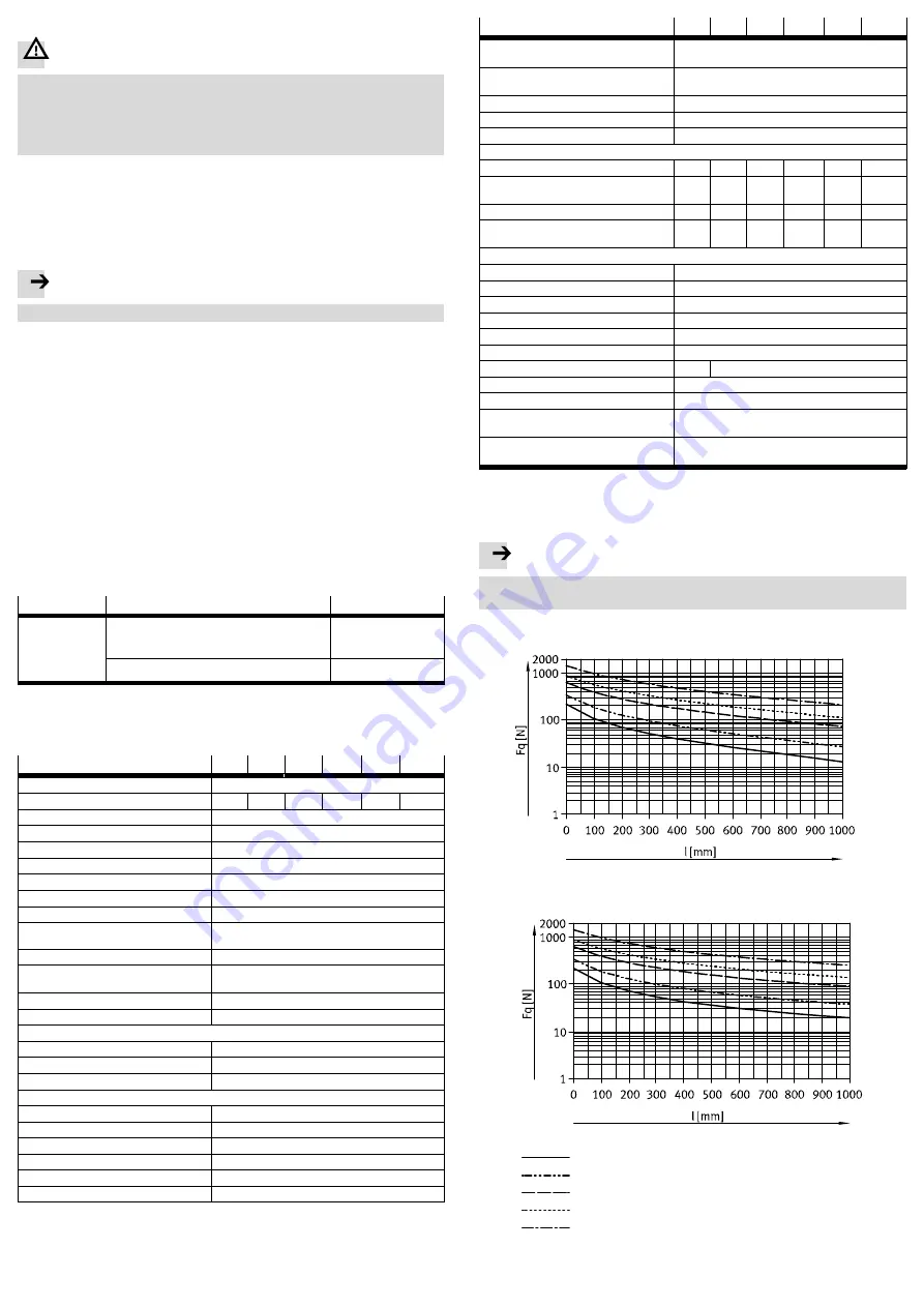
Max. permissible lateral force for static application
Note
In controlled operation, adjustment of the max. lateral force to the type of con
trol may be required.
Horizontal installation
Vertical installation
Ø 100
Ø 125
Ø 160/200
Ø 250
Ø 320
Fig. 10


