Alternatively, certain settings can be made via the ‘Festo Field Device Tool’ (FFT) or
via the ‘Festo Automation Suite’ (FAS).
1. Connect the gateway to a PC or notebook via the ‘Device’ network connection.
2. Call the web server:
https://<IP_address_of_the_network_connection_‘Device’>
Ä
The warning that the web server does not have a secure SSL certificate is
displayed.
A server certificate suitable for the IT infrastructure can be installed in
the ‘Configuration’ > ‘Web server SSL certificate’ menu bar.
3. Logging in:
–
User name: admin
–
Password (factory setting): CPX-IOT Product Key on the type plate,
e.g. 3S7PMM2M93V
7.3
Configuring MQTT broker
1. Call the web server:
https://<IP_address_of_the_network_connection_‘Device’>
2. To parameterise the MQTT broker, select ‘MQTT’
>
‘Broker Configuration’ in
the menu bar.
3. To perform a connection test, select ‘MQTT’
>
‘Send Test Message’ in the
menu bar.
7.4
Configure field device or IOT data source
1. Call the web server:
https://<IP_address_of_the_network_connection_‘Device’>
2. To configure field devices or IOT data sources, select ‘Devices’
>
‘Manage
Devices’ in the menu bar.
7.5
Querying firmware information
The firmware version and firmware updates can be queried via the
‘Festo Field Device Tool’ (FFT) or the ‘Festo Automation Suite’ (FAS).
7.6
Performing firmware update
Firmware, software or configuration files
1. Enter ‘Festo Field Device Tool’ into search.
2. Select software in the ‘Software/Downloads’ section.
3. Download and install the current version of the ‘Festo Field Device Tool’.
8
Malfunctions
8.1
Diagnostics
8.1.1
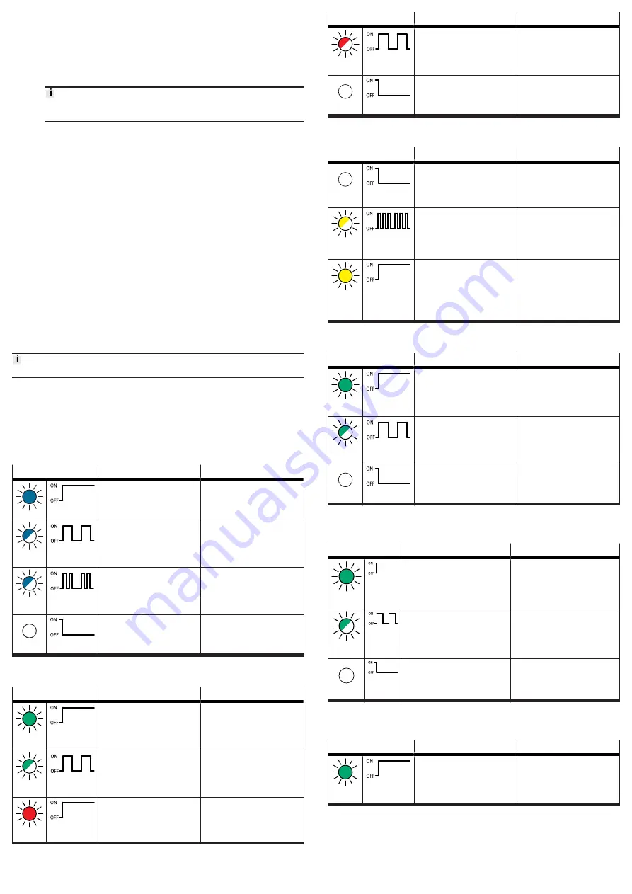
‘Cloud’ network status
LED status
Meaning
Error handling
blue light
Normal operating status:
Network connection to MQTT
broker established.
—
flashes
blue 1x
Establishment or restoration of a
connection to the MQTT broker.
—
flashes
blue 2x
Network error
–
Check configuration,
e.g.
DHCP address assignment,
static IP address.
off
No connection to the MQTT
broker.
–
Check network connection.
Tab. 9: ‘Cloud’ network status (LED with cloud symbol)
8.1.2
‘Device’ network status
LED status
Meaning
Error handling
green
light
Normal operating status:
The gateway is connected with
field devices.
—
flashing
green
No connection to field devices:
The gateway has received an IP
address, but is not yet connected
with field devices.
–
Check configuration.
–
Check module status.
–
Restart module.
–
Repeat Onboarding.
red light
Communication with the field
devices has failed:
non-permitted network configura-
tion, e.g. already used IP address
set.
–
Check configuration,
e.g.
DHCP address assignment,
static IP address.
LED status
Meaning
Error handling
flashing
red
Communication with the field
devices has failed:
Network connection faulty,
e.g. connecting cable interrupted.
–
Check device connection.
off
The gateway is offline.
–
Check network connection.
Tab. 10: ‘Device’ network status ([NS] LED)
8.1.3
Module status
LED status
Meaning
Error handling
off
Normal operating status:
The gateway is in the [Off ], [Read
only] or [Read/Write]
switch for the operating mode
operating mode
—
flashes
yellow 3x
Onboarding devices active:
The gateway performs a network
scan.
The gateway is in the [Read/
Write] operating mode
switch for the operating mode.
—
yellow
light
The gateway is in the [Off ] or
[Onboarding] operating mode.
There is no communication with
the MQTT broker and no com-
munication with field devices
–
Set rotary switch to [Read only]
or [Read/Write].
Tab. 11: Module status ([M] LED)
8.1.4
‘Cloud’ connection status
LED status
Meaning
Error handling
green
light
Normal operating status:
Network connection established.
–
flashing
green
Data traffic
1)
–
off
No network connection
–
Check network connection.
1) The flashing frequency depends on the traffic.
Tab. 12: ‘Cloud’ connection status ([TP1] LED)
8.1.5
‘Device’ connection status
LED status
Meaning
Error handling
green
light
Normal operating status:
Network connection to the field
devices has been established.
–
flashing
green
Data traffic
1)
–
off
No network connection
–
Check network connection.
1) The flashing frequency depends on the traffic.
Tab. 13: ‘Device’ connection status ([TP2] LED)
8.1.6
‘operating power supply’ status
LED status
Meaning
Error handling
1)
green
light
Normal operating status:
Operating voltage applied.
–


