


2
Product overview
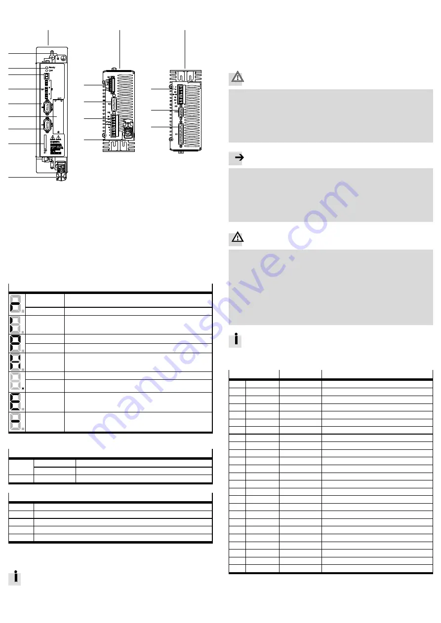
2.1 Device view
1
2
3
4
5
6
7
8
9
aJ
aA
aB
aC
aD
aE
aF
aG
aH
aE
1
Front view
2
Bottom view
3
Top view
4
Earthing screw (central PE
connection)
5
LED status display
6
7-segments display
7
[S1]: DIP switch
8
[X5]: RS232/RS485
9
[EXT]: Slot for CAMC-...
aJ
[X4]: CAN bus
aA
[M1]: SD memory card
aB
[X3] STO interface
aC
[X2] Encoder
aD
[X6] Motor
aE
Shield connection terminal
aF
[X9] Power supply
aG
[X10] Master/Slave
aH
[X1] I/O interface
Fig. 1
Motor controller CMMS-AS-...-G2
2.2 Display and control elements
7-segments display
1)
Rotating outside
segments
Speed mode (speed adjustment):
Display changes corresponding to rotor position and speed.
Middle segment
Controller enable active (motor is energised).
I
Force mode (current control).
P x x x
Positioning mode, record number x x x
P H x
Homing phase x
H
Two-channel safety function requested (DIN4 [X1.21] and Rel [X3.2]).
Point
Start program (Bootloader) active.
Flashing point
– Firmware file (memory card) is being read.
– Display of errors through the start program.
E x x y
Error (E = error)
Number: Two-position main index (x x), single-position subindex (y)
Example: E 0 1 0
section 7.
– x x y –
Warning
Number: Two-position main index (x x), single-position subindex (y).
Example: - 1 7 0 -
section 7.
1)
Several characters are displayed one after the other.
LED display
Ready
Green
Operating status/controller enable
Flashing green
Parameter file (memory card) is being red/written
CAN
Yellow
Status display: CAN bus active
DIP switch
S1.1 … 7
CAN bus address or MAC-ID
S1.8
Automatic loading of new firmware and parameter files from memory card
S1.9 … 10
Setting the CAN-bus transmission rate
S1.11
Activation of the CAN-bus interface
S1.12
Terminating resistor for CAN-bus
3
Mechanical installation
3.1 Assembly
Observe the information on the installation dimensions and free spaces in
the
hardware description GDCP-CMMS-AS-G2-HW-...
For vertical mounting onto a control cabinet mounting plate:
• Mount the accompanying mounting bracket to the motor controller.
• Use the motor controller exclusively in a control cabinet:
– The mounting position is vertical with the power supply lines [X9] leading
upwards.
– Mounting to the mounting brackets with M5 screws.
4
Electrical installation
Caution
Danger from unexpected movement
Faulty pre-assembled lines may destroy the electronics and trigger unexpected
movements of the motor.
• When wiring the system, use only the supplied plug connectors and preferably
the cables listed in the catalogue as accessories.
www.festo.com/catalogue
• Lay all flexible lines so that they are free of kinks and free of mechanical
stress; if necessary use chain link trunking.
Note
ESD (electrostatic discharge) can cause damage to the device or other system
parts at plug connectors that are not used.
• Before installation: Earth the system parts and use appropriate ESD equip-
ment (e.g. shoes, earthing straps etc.).
• After installation: Seal unassigned D-sub plug connectors with protective caps
(available at authorized dealers).
• Observe the handling specifications for electrostatically sensitive devices.
Warning
Danger of electric shock
Motor controllers are devices with increased leakage current (
>
10 mA). If wiring
is incorrect or the device is defective, high voltage can occur on the housing,
which can result in serious injury or even death if the housing is touched.
• Before commissioning, also for brief measuring and test purposes, connect
the PE protective conductor:
– to the earthing screw of the controller housing,
– to pin PE [X9.5], power supply. The cross section of the protective conduct-
or at PE [X9.5] must correspond at least to the cross section of the external
conductor L [X9.1].
• Observe the regulations of EN 50178 and IEC 60204-1.
Observe the information on safe and EMC-suitable installation and on
protective earthing in the Hardware description GDCP-CMMS-AS-G2-HW-...
4.1 I/O interface [X1]
Pin
Value
Assignment in 0 mode – positioning
1
SGND
0 V
Screening for analogue signals
2
DIN12/AIN0
–
Mode bit 0/
setpoint input 0
2)
3
DIN 10
–
Record selection bit 4 (high active)
4
+VREF
+10 V ±4 %
Reference output for setpoint value potentiometer
5
–
–
–
6
GND24
–
Reference potential for digital I/O modules
7
DIN 1
–
Record selection bit 1 (high active)
8
DIN 3
–
Record selection bit 3 (high active)
9
DIN 5
–
Controller enable (high active)
10
DIN 7
–
Limit switch 1
11
DIN 9
–
Mode bit 1
12
DOUT1
24 V 100 mA
Motion complete (high active)
1)
13
DOUT3
24 V 100 mA
Common error (low active)
1)
14
AGND
0 V
Reference potential for analogue signals
15
DIN13/#AIN0
–/Ri = 20 kΩ
Stop (low active)/reference potential AIN0
2)
16
DIN 11
–
Record selection bit 5 (high active)
2)
17
AMON0
0 … 10 V ±4 %
Output: analogue monitor 0
18
+ 24 V DC
24 V 100 mA
Output: 24 V DC, looped through from [X9.6]
19
DIN 0
–
Record selection bit 0 (high active)
20
DIN 2
–
Record selection bit 2 (high active)
21
DIN 4
–
Output stage enable (high active)
22
DIN 6
–
Limit switch 0
23
DIN 8
–
Start for the positioning procedure (high active)
24
DOUT0
24 V 100 mA
Output: Controller ready for operation (high active)
25
DOUT2
24 V 100 mA
Start acknowledged (low active)
1)
1)
Default setting, configurable in the Festo Configuration Tool (FCT).
2)
Pin allocation with control via analogue input


