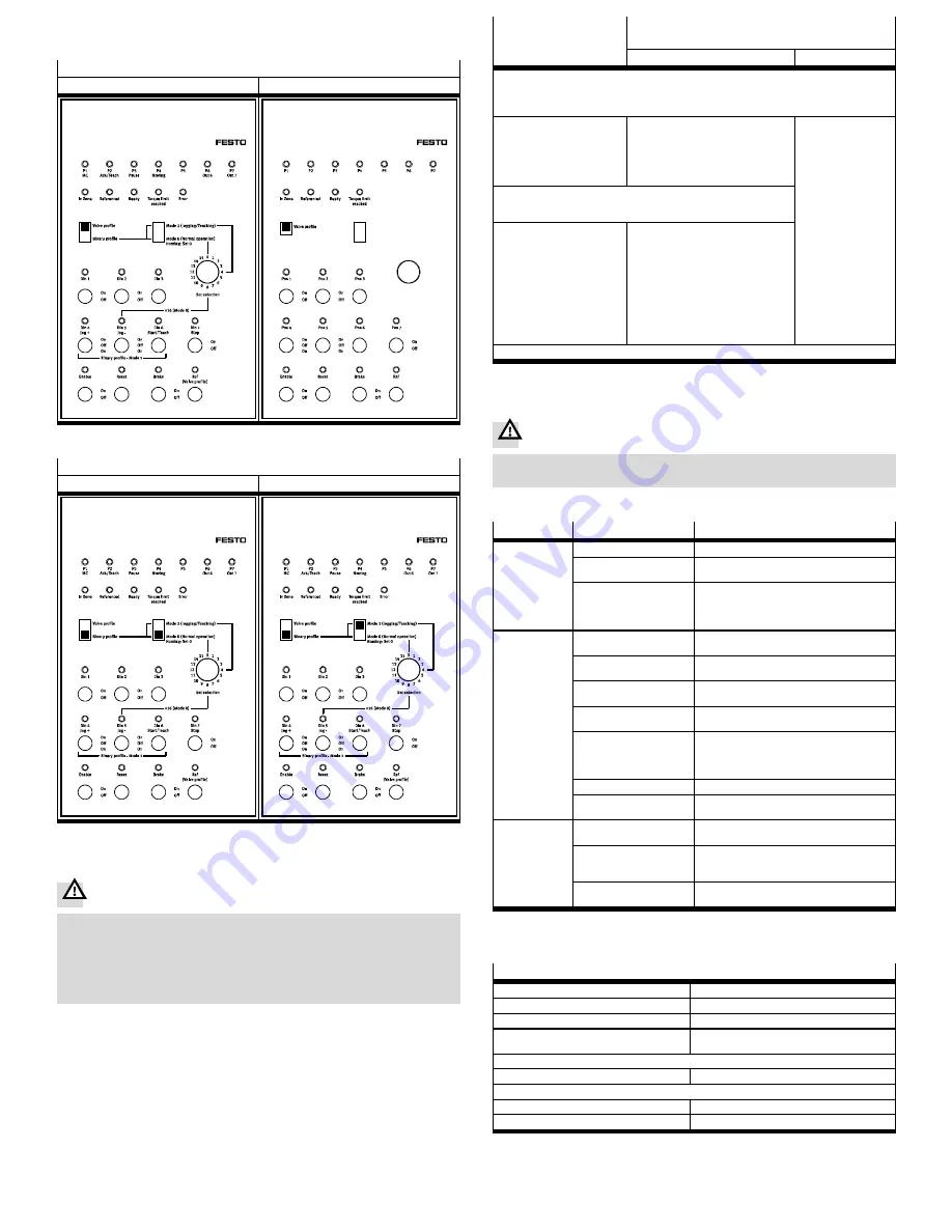
• Slide the selector switches
2
and
3
into the required basic setting for your
desired control profile:
Control profile: Valve profile
Basic setting
Template as adjustment aid
2
2
Fig. 3
Control profile: Binary profile
Mode 0 (normal operation)
Mode 1 (jog/teach operation)
2
3
2
3
Fig. 4
5.2 Commissioning – processing
Warning
Modification to the signal statuses with the simulator can trigger dangerous
movements of the connected actuators.
• Make sure that nobody is in the sphere of influence of the connected actuat-
ors and be very careful with manipulation of signal statuses.
• Make sure that the toggle switch
8
(controller enable) is set to “Off ”.
The “Enable” LED is not lit.
Control profile:
Valve profile
Control profile:
Binary profile
Mode 0
Mode 1
• Make sure that all toggle switches
5
to
9
are set to “Off ”.
• Set the selector switch for the control profile to the desired position.
• Energise the controller.
• Issue controller enable by setting the toggle switch
8
to “On”
• Start homing by setting the
toggle switch
5
to “On”.
Resetting the toggle switch
5
to “Off ” interrupts hom-
ing
• Set the toggle switch “Din 7/Stop”
to “On”.
• Start homing by setting the rotary
switch
4
to “0” and then actuating
the toggle switch “Din 6/Start/
Teach”
• Set the toggle
switch “Din 7/
Stop” to “On”.
• Start a movement
in the positive or
negative direction
by actuating the
toggle switch
“Din 4/Jog+” or
“Din 5/Jog-”.
• The drive carries
out the movement
as long as the
toggle switch is at
“On”
• Check whether the actuator reacts as expected.
When homing has been completed successfully, the “Referenced” LED
is illuminated continuously
• Start one of the position
sets 1 – 7 by setting the cor-
responding toggle switch
9
to “On”.
• You can stop the movement
by setting the correspond-
ing switch back to “Off ”
• Start one of the position sets 1 – 31
by setting the rotary switch
4
to
the desired record number (to select
the records 16 – 31, the toggle
switch “Din 5/Jog-” must also be set
to “On”).
• Then actuate the toggle switch
“Din 6/Start/Teach”.
• You can interrupt the movement by
setting the toggle switch
“Din 7/Stop” to “Off ”
• Check whether the actuator reacts as expected
Fig. 5
6
Disassembly
Warning
Dangerous movements of the connected actuator technology
• Disconnect the connections only in the de-energised status.
7
Fault clearance
Malfunction
Possible cause
Remedy
Controller does
not react to digit-
al input signals or
does not indicate
the signal
statuses
Controller is not energised
Energise the controller
Unequal switching logic at
simulator and controller
Use equal switching logic (e.g. PNP simulator
CDSM-S3-P with PNP controller CMMO-...-DIOP)
The electrical connection
between controller and
simulator is damaged/de-
fective
Check the connecting cable between controller
and simulator for damage/broken cable. Use
only the supplied cable from Festo
Controller does
not react to start/
positioning com-
mand
Incorrect control profile or
mode selected
Check the settings of the selector switch
2
and
3
Invalid record selected
Check whether the selected set has been para-
meterised in the positioning record table
Positioning record table
not yet created
Parameterise positioning record table via FCT or
Webserver
Stop input active
Only in the binary profile: Check whether the
toggle switch “Din 7/Stop” is at “On”
Controller in the error
status
Check whether the “Error” LED is lit (only in the
binary profile). Determine the cause of error/er-
ror code, if necessary. Acknowledge the error
after eliminating the cause
Controller not approved
Check whether the toggle switch
8
is at “On”
Controller not paramet-
erised
Parameterise controller via FCT or Webserver
Drive does not re-
act as expected
Incorrect control profile or
mode selected
Check the settings of the selector switch
2
and
3
Incorrect positioning record
selected
Especially in the binary profile: Check the set-
ting on the rotary switch
4
and on the toggle
switch “Din 5/Jog-”
Invalid position set selec-
ted
Check whether the selected set has been para-
meterised in the positioning record table
Fig. 6
8
Technical data
CDSM-S3-P/-N
Ambient temperature
[°C]
0 … +40
Mounting position
Any
Degree of protection
IP20
Digital inputs (OUT1 ... OUT11)
Digital outputs (DIN1 ... DIN11)
Are provided through the connected controller
(
documentation on the controller)
Dimensions:
Width/depth/height
[mm]
106/176/54.3
Materials:
Housing
Acrylonitrile butadiene styrene
Weight
[g]
290
Fig. 7


