background image

Festo  GDSP−CDSA−SY−ML    0805NH    Deutsch

7

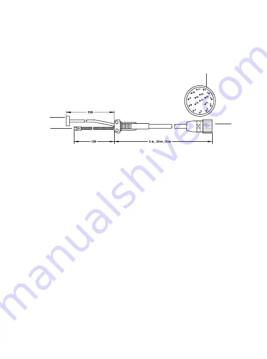
3.3 Kabel  NESC−C−D1−x−C1

Zum  Anschluss  des  Bediengerätes  CDSA  an  die  Anschalt
box  sind  3  Kabel  mit  unterschiedlichen  Längen  verfügbar.

2

3

1

1

1

Anschluss  an  CAMI−I

2

Ethernetanschluss

3

Anschluss  für  Spannungs
versorgung,  NOT−AUS  und
Zustimmtaster

Summary of Contents for CDSA-D1-VX

Page 1: ...Kurz bersicht Brief overview CDSA D1 VX Deutsch English Espa ol Fran ais Italiano Svenska 729 255 0805NH Bedienger t Operator unit CDSA...

Page 2: ...ML 0805NH 2 Deutsch 3 English 13 Espa ol 23 Fran ais 33 Italiano 43 Svenska 53 Edition 0805NH Original de Festo AG Co KG D 73726 Esslingen Germany 2008 Internet http www festo com E Mail service_inter...

Page 3: ...inem gro en farbigen Touch Screen und intuitiv bedienbaren Funktonstasten ausgestattet Hinweis Diese Kurz bersicht ist Teil des Dokumentationspake tes Sie dient nur zur Erstinformation und ersetzt nic...

Page 4: ...eutsch 4 2 Gesamt bersicht 2 1 3 4 5 6 7 1 Schaltschrank 2 MehrachssteuerungCMXR C1 3 Ethernet Leitung Crossover Ethernet Leitung mit Switch 4 Anschaltbox CAMI C 5 Br ckenstecker CAMF B 6 Kabel NESC C...

Page 5: ...1 VX sind um das zentrale farbige TFT Display herum 3 Funktionstasten Gruppen und der NOT AUS Knopf angeordnet Die Bedienung des Touch Screen erfolgt mit Hilfe des beiliegenden Stifts 2 3 4 5 6 1 1 NO...

Page 6: ...C Das Handbedienger t wird ber die Anschaltbox CAMI C an die CMXR Mehrachssteuerung angeschlossen 2 3 4 5 1 1 Ethernet Anschluss 2 Anschluss f r NOT AUS Spannungsversorgungund Zustimmtaster 3 Nicht in...

Page 7: ...Kabel NESC C D1 x C1 Zum Anschluss des Bedienger tes CDSA an die Anschalt box sind 3 Kabel mit unterschiedlichen L ngen verf gbar 2 3 1 1 1 Anschluss an CAMI I 2 Ethernetanschluss 3 Anschluss f r Span...

Page 8: ...Handbedienger t nicht zwingend erforderlich Nach den Programmier und Inbetriebnahmearbeiten kann das Handbedienger t abgesteckt werden Da die Signale f r NOT AUS ber das Handbedienger t gef hrt werde...

Page 9: ...ung CAFM D1 W Die Wandhalterung dient zum station ren Betrieb oder zur Ablage des Handbedienger tes CDSA Die Kabelhalterung dient der Ablage des Kabels NESC C D1 2 3 1 1 1 Bohrl cher zur Wand befestig...

Page 10: ...lt Typ Teilenummer Hardwarebeschreibung CDSA GDCP CDSA SY DE GDCP CDSA SY EN GDCP CDSA SY ES GDCP CDSA SY FR GDCP CDSA SY IT GDCP CDSA SY SV 560333 560334 560335 560336 560337 560338 Softwarebeschreib...

Page 11: ...ationsverbindungzuCMXR C1vorhanden Error rot Es steht eine Fehlermeldung an die quittiert werden muss Motion gr n Antriebe sind in Regelung Process Zur Zeit nicht genutzt 5 2 Diagnose vor Ort ber Disp...

Page 12: ...bereich 19 30 V DC Stromaufnahme 0 4 A Schutzart IP65 Produktgewicht 1250 g Temperaturbereich Lagerung 20 70 C Temperaturbereich Betrieb 0 50 C Relative Luftfeuchtigkeit 5 95 Anwenderspeicher 256 MByt...

Page 13: ...the device is equipped with a large colour touch screen and function keys that can be operated intuitively Note This brief overview is part of the documentation pack age It serves only as initial info...

Page 14: ...ish 14 2 General overview 2 1 3 4 5 6 7 1 Control cabinet 2 CMXR C1 multi axis controller 3 Ethernet cable crossover Ethernet cable with switch 4 CAMI C interface unit 5 CAMF B jumper plug 6 NESC C D1...

Page 15: ...ndheld operator unit there are three function key groups and the EMERGENCY STOP button arranged around the central colour TFT display The touch screen is operated using the supplied pen 2 3 4 5 6 1 1...

Page 16: ...The handheld operator unit is connected to the CMXR multi axis controller via the CAMI C interface unit 2 3 4 5 1 1 Ethernet connection 2 Connection for EMERGENCY STOP power supply and enablingswitch...

Page 17: ...ESC C D1 x C1 cable Three cables with various lengths are available for connecting the CDSA operating unit to the interface unit 2 3 1 1 1 Connection to CAMI I 2 Ethernet connection 3 Connection for p...

Page 18: ...absolutely required for such operation The handheld operator unit can be disconnected after the programming and commissioning work Because the signals for EMERGENCY STOP are transmitted via the operat...

Page 19: ...1 W wall holder The wall holder is used for stationary operation or for holding the CDSA handheld operator unit The cable holder is used to hold the NESC C D1 cable 2 3 1 1 1 Drill holesfor wall mount...

Page 20: ...ts Type Part number CDSA hardware description GDCP CDSA SY DE GDCP CDSA SY EN GDCP CDSA SY ES GDCP CDSA SY FR GDCP CDSA SY IT GDCP CDSA SY SV 560333 560334 560335 560336 560337 560338 CDSA software de...

Page 21: ...unication connection to the CMXR C1 exists Error red An error message is active that has to be acknowledged Motion green Drives are under control Process Not used at present 5 2 On site diagnosis with...

Page 22: ...oltage range 19 30 V DC Currentconsumption 0 4 A Protection class IP65 Product weight 1250 g Temperature range storage 20 70 C Temperature range operation 0 50 C Relative air humidity 5 95 User memory...

Page 23: ...las Para ello la unidad est provista de una gran pantalla t ctil en color y teclas de funci n de manejo intuitivo Importante Este cuadro general resumido forma parte del conjunto de la documentaci n S...

Page 24: ...leto 2 1 3 4 5 6 7 1 Armario de maniobra 2 Unidad de control multieje CMXR C1 3 Cable de Ethernet Crossover cable de Ethernet con interruptor 4 Caja de conexi n CAMI C 5 Conector puente CAMF B 6 Cable...

Page 25: ...ne de 3 grupos de teclas de funci n y un bot n de PARO DE EMERGENCIA dispuestos alrededor de la pantalla central de TFT en color El manejo de la pantalla t ctil se realiza con el l piz suministrado 2...

Page 26: ...ndicaci n y control se conecta al control multieje CMXR mediante la caja de conexi n CAMI C 2 3 4 5 1 1 Conexi n Ethernet 2 Conexi n para PARO DE EMERGENCIA alimentaci n y pulsador de autorizaci n 3 N...

Page 27: ...1 x C1 Para conectar la unidad de indicaci n y control CDSA a la caja de conexi n est n disponibles 3 cables de distintas longitudes 2 3 1 1 1 Conexi n a CAMI I 2 Conexi n de Ethernet 3 Conexi n para...

Page 28: ...indicaci n y control Despu s de realizar los trabajos de programaci n y puesta a punto se puede retirar la unidad Dado que las se ales de PARO DE EMER GENCIA se dirigen desde la unidad manual de indic...

Page 29: ...ral sirve para funcionamiento estacionario o para depositar la unidad manual de indicaci n y control DSA El soporte del cable sirve para depositar el cable NESC C D1 2 3 1 1 1 Taladros para la fijaci...

Page 30: ...po N de art culo Descripci n del hardware CDSA GDCP CDSA SY DE GDCP CDSA SY EN GDCP CDSA SY ES GDCP CDSA SY FR GDCP CDSA SY IT GDCP CDSA SY SV 560333 560334 560335 560336 560337 560338 Descripci n del...

Page 31: ...n de comunicaci n con CMXR C1 Error rojo Hay un mensaje de error que debe ser validado Movimiento verde Los accionamientos est n en regulaci n Process Actualmente no utilizado 5 2 Diagnosis local med...

Page 32: ...de corriente 0 4 A Clase de protecci n IP65 Peso del producto 1250 g Margen de temperatura almacenamiento 20 70 C Margen de temperatura funcionamiento 0 50 C Humedad relativa del aire 5 95 Memoria de...

Page 33: ...L appareil est quip d un grand cran tactile couleur et de touches de fonction intuitives Nota Cette notice simplifi e fait partie int grante de la docu mentation Elle sert uniquement une premi re inf...

Page 34: ...ais 34 2 Vue d ensemble 2 1 3 4 5 6 7 1 Armoire de commande 2 Commande multi axes CMXR C1 3 C ble Ethernet crois Switch Ethernet 4 Bo tier de couplage CAMI C 5 Cavalier CAMF B 6 C ble NESC C D1 x C1 7...

Page 35: ...CDSA D1 VX 3 groupes de touches de fonction et le bouton d arr t d urgence sont dispos s autour de l cran couleur TFT central L cran tactile doit tre utilis l aide du stylet fourni 2 3 4 5 6 1 1 ARRE...

Page 36: ...manuel est raccord la commande multi axes CMXR par l interm diaire du bo tier de couplage CAMI C 2 3 4 5 1 1 Connecteur Ethernet 2 Connecteur pour arr t d urgence alimentation lectrique et touche de...

Page 37: ...x C1 3 c bles de longueurs diff rentes sont disponibles pour raccorder le terminal de commande CDSA au bo tier de couplage 2 3 1 1 1 Raccordement au CAMI I 2 Connecteur Ethernet 3 Connecteur pour ali...

Page 38: ...able Une fois les op rations de programmation et de mise en service effectu es le terminal de commande manuel peut tre d branch Les signaux d arr t d urgence tant transmis par l interm diaire du termi...

Page 39: ...ral est destin accueillir le terminal de commande manuel CDSA lorsqu il n est pas utilis ou s il est utilis depuis un point fixe L attache de c ble accueille quant elle le c ble NESC C D1 2 3 1 1 1 Tr...

Page 40: ...isponible Contenu Type R f rence Manuel mat riel CDSA GDCP CDSA SY DE GDCP CDSA SY EN GDCP CDSA SY ES GDCP CDSA SY FR GDCP CDSA SY IT GDCP CDSA SY SV 560333 560334 560335 560336 560337 560338 Manuel l...

Page 41: ...le CMXR C1 tablie Error rouge Un message d erreur pr sent doit tre valid Motion verte Les entra nements sont en cours de r gulation Process Actuellementinutilis 5 2 Diagnostic sur place via l cran Lo...

Page 42: ...rvice 19 30 V CC Intensit absorb e 0 4 A Indice de protection IP65 Poids du produit 1250 g Plage de temp rature stockage 20 70 C Plage de temp rature service 0 50 C Humidit relative de l air 5 95 M mo...

Page 43: ...ti Perci l unit equipaggiata con un grande touchscreen a colori e tasti funzione a gestione intuitiva Nota Questa breve panoramica parte integrante del pacchetto di documentazione Serve solo come prim...

Page 44: ...ica generale 2 1 3 4 5 6 7 1 Armadio elettrico 2 Comando multiasse CMXR C1 3 Conduttore Ethernet crossover conduttore Ethernet con switch 4 Scatola di connessione CAMI C 5 Connettore a ponte CAMF B 6...

Page 45: ...i dell unit CDSA D1 VX sono sistemati 3 gruppi di tasti funzione e il tasto di STOP D EMERGENZA Il touchscreen viene gestito con l ausilio della penna in dotazione 2 3 4 5 6 1 1 STOP EMERGENZA 2 Penna...

Page 46: ...viene collegata al comando multiasse CMXR tramite la scatola di connessione CAMI C 2 3 4 5 1 1 ConnessioneEthernet 2 Connessione per STOP D EMERGENZA alimentazione elettrica e tasto di consenso 3 Non...

Page 47: ...SC C D1 x C1 Sono disponibili 3 cavi di lunghezza diversa per collegare l unit di comando CDSA alla scatola di connessione 2 3 1 1 1 Connessionea CAMI I 2 ConnessioneEthernet 3 Connessioneper alimenta...

Page 48: ...l unit CDSA non necessaria L unit pu essere disinnestata dopo le operazioni di programmazione e messa in servizio Dopo il disinnesto bisogna cavallottare i segnali perch questi vengono trasmessi trami...

Page 49: ...parete CAFM D1 W Il supporto da parete viene utilizzato per l esercizio fisso o come piano di appoggio per l unit CDSA Il portacavo viene utilizzato come supporto del cavo NESC C D1 2 3 1 1 1 Fori per...

Page 50: ...Codice prodotto Descrizione dell hardware CDSA GDCP CDSA SY DE GDCP CDSA SY EN GDCP CDSA SY ES GDCP CDSA SY FR GDCP CDSA SY IT GDCP CDSA SY SV 560333 560334 560335 560336 560337 560338 Descrizione de...

Page 51: ...comunicazione a CMXR C1 presente Error rosso presente un messaggio di errore da tacitare Motion verde Gli attuatori sono in fase di regolazione Process Attualmente non utilizzato 5 2 Diagnosi in loco...

Page 52: ...bimento di corrente 0 4 A Grado di protezione IP65 Peso 1250 g Intervallo di temperatura magazzinaggio 20 70 C Intervallo di temperatura esercizio 0 50 C Umidit relativa dell aria 5 95 Memoria utente...

Page 53: ...har panelen en stor och f rgpeksk rm och intuitivt anv ndbara funktionsknappar Information Denna snabb versikt r en del av dokumentations paketet Den inneh ller endast versiktsinformation och ers tter...

Page 54: ...venska 54 2 versikt 2 1 3 4 5 6 7 1 Kopplingssk p 2 FleraxelstyrsystemCMXR C1 3 Ethernet ledning Crossover Ethernet ledning med switch 4 InkopplingsboxCAMI C 5 BryggkontaktdonCAMF B 6 Kabel NESC C D1...

Page 55: ...anelen CDSA D1 VX sitter tre grupper med funktionsknappar och n dstoppsknappen runt den centralt placerade f rg TFT displayen Peksk rmen anv nds med hj lp av det bifogade stiftet 2 3 4 5 6 1 1 N dstop...

Page 56: ...x CAMI C Handoperat rspanelen ansluts via inkopplingsboxen CAMI C till CMXR fleraxelstyrsystemet 2 3 4 5 1 1 Ethernet anslutning 2 Anslutningf r n dstopp sp nningsf rs rjningoch godk nnandeknapp 3 Anv...

Page 57: ...3 3 Kabel NESC C D1 x C1 Det finns 3 kablar av olika l ngd f r att ansluta operat rspanelen CDSA till inkopplingsboxen 2 3 1 1 1 Anslutningtill CAMI I 2 Ethernet anslutning 3 Anslutningf rsp nnings f...

Page 58: ...ste inte handoperat rspanelen anv ndas Efter programmering och idrifttagning kan handoperat rspanelen kopplas loss N r den har kopplats loss beh vs en verkoppling av signalerna eftersom signalerna f...

Page 59: ...gh llare CAFM D1 W V ggh llaren r till f r station r drift eller som f rvaringsplats f r handoperat rspanelen CDSA Kabelh llaren r till f r att h lla kabeln NESC C D1 2 3 1 1 1 Borrh l f r v ggf ste 2...

Page 60: ...rtikelnummer Maskinvarubeskrivning CDSA GDCP CDSA SY DE GDCP CDSA SY EN GDCP CDSA SY ES GDCP CDSA SY FR GDCP CDSA SY IT GDCP CDSA SY SV 560333 560334 560335 560336 560337 560338 Mjukvarubeskrivning CD...

Page 61: ...Run gr n Kommunikationsf rbindningmedCMXR C1finns Error r d Det finns ett felmeddelande som m ste kvitteras Motion gr n Drivenheter regleras Process Anv nds inte f r n rvarande 5 2 Diagnos direkt p pl...

Page 62: ...ngsomr de 19 30 V DC Str mf rbrukning 0 4 A Kapslingsklass IP65 Produktensvikt 1250 g Temperaturomr de f rvaring 20 70 C Temperaturomr de drift 0 50 C Relativ luftfuktighet 5 95 Anv ndarminne 256 MByt...

Page 63: ......

Page 64: ...75939...

Reviews: