


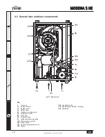

MODENA S HE
14
EN
cod. 3541C364 - Rev. 00 - 12/2012
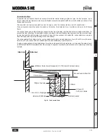
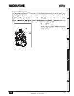
2.6 Flue system
This unit is a "C type" with
sealed chamber
and forced draught, with air inlet and flue exhaust to be connected to one
of the following flue systems. Before installation, with the aid of the tables and calculation methods given, check that the
pipes of the fume system do not exceed the maximum permissible lengths. The current standards and local regulations
must be observed.
B
Only a Ferroli flue system (with respective accessories) must be used with this unit, as required by BS 5440
and CE standards.
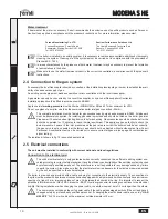
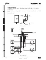
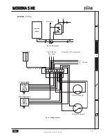
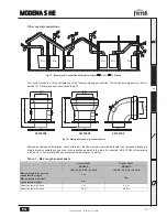
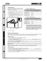
Connection with coaxial pipes
Standard connection with coaxial pipes (code 041049G0)
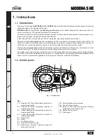
fig. 17 - Standard connection
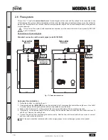
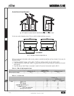
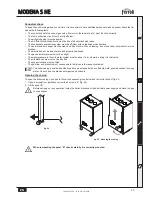
Horizontal flue installation
1. Define the position for installing the unit.
2. If using standard flue (
041049G0
) this must be installed level. For extended horizontal flue lengths over 1m a fall of
3 mm per metre of the flue exhaust should be incorporated back to the boiler.
3. Make a hole of diameter 10 - 20 mm greater than the nominal diameter of the concentric pipe used.
4. If necessary, cut the terminal length to size, ensuring that the external pipe protrudes from the wall by between 10
and 60 mm. Remove the cutting burrs.
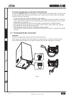
5. Connect flue to the boiler, positioning the seals correctly. Seal the flue into the wall with silicone or sand + cement
and cover with wall seals provided.
A
Flue seals should be lubricated with a silicone type grease to prevent damage (grease not supplied).
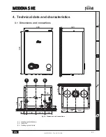
Between
10 e 60 mm
Between
10 e 60 mm
320
125
200
80
600
Ø100
125
110
80
600
Ø100
Drill the wall 10÷20 mm
more than the
pipe diameter
Rear outlet
Side view
Side outlet
Front view
200
400


