Not for
Reproduction
30
brake, turn the ignition switch to OFF, and remove the
ignition key.
2. Chock the front wheels of the unit to prevent movement
and disengage the parking brake.
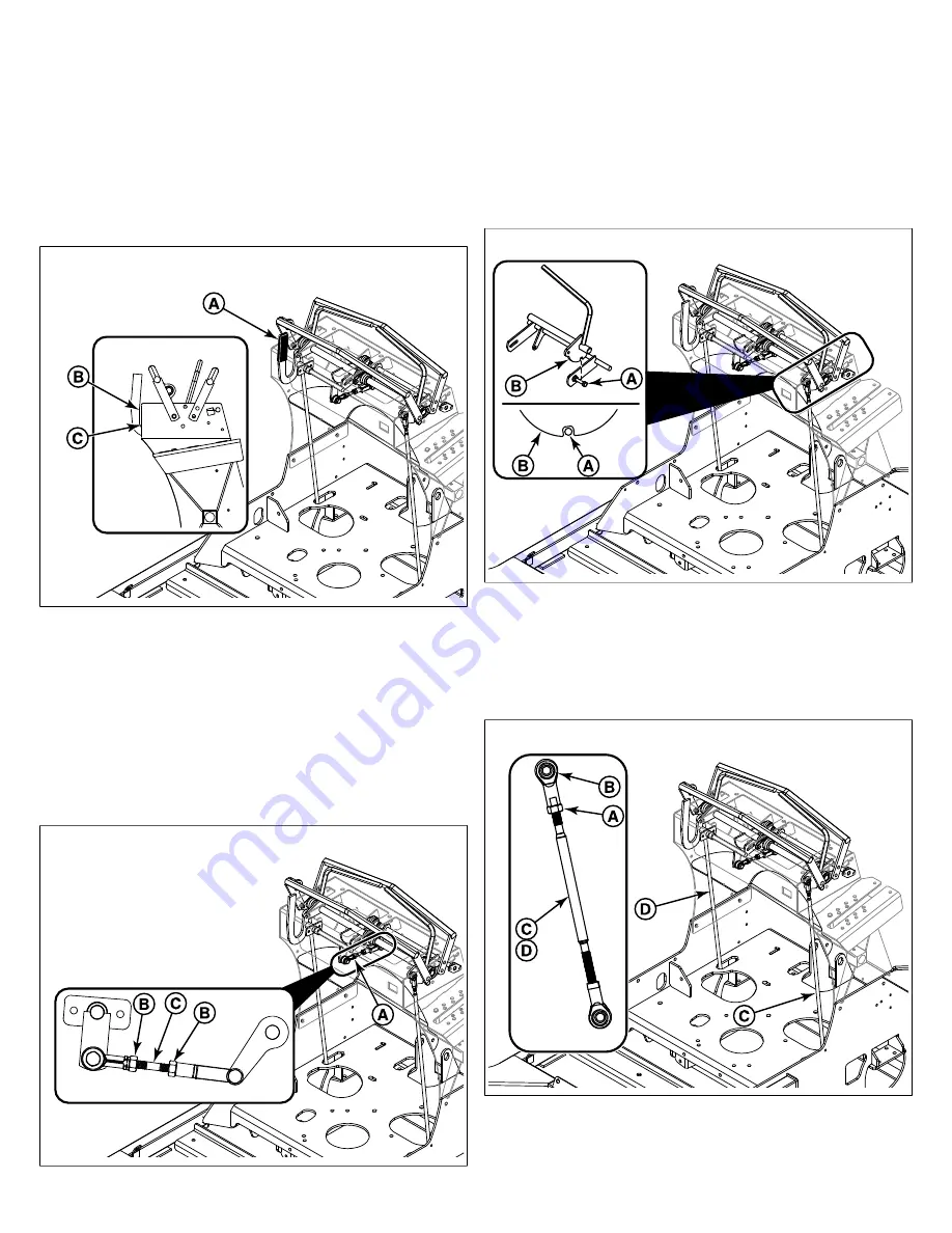
3. Engage the parking brake by pulling the parking brake
lever (A, Figure 39) up and back while moving both
ground speed control levers forward back and forth, so
that the neutral lockouts will engage the ground speed
control levers as the parking brake is being engaged.
39
4. With the parking brake engaged observe the flat edge of
the parking brake lever (B) in relation to the front of the
dash panel (C). The front edge of the parking brake lever
should be parallel to the front of the dash panel.
5. To adjust the position of the parking brake lever: Locate
the threaded linkage rod (A, Figure 40) that connects the
parking brake lever to the neutral lockout shaft. Loosen
the two jam nuts (B) and turn the rod (C) until the flat
edge of the parking brake lever is parallel to the front of
the dash panel.
40
6. Tighten the jam nuts.
Left Hand Side Lockout Bolt Adjustment
1. Observe the left hand side lockout bolt (A, Figure 41).
It should be positioned so that it is in the center of the
notch of the lockout plate (B) on the ground speed control
lever.
41
2. To adjust the position of the left hand side lockout bolt in
the notch of the lockout plate on the ground speed control
lever, loosen the jam nut (A, Figure 42) tightened against
the upper ball joint (B) on the left hand side motion control
rod (C) and turn the rod until the left hand side lockout
bolt is in the center of the notch of the lockout plate.
42
3. Re-tighten the jam nut.


