background image

FERNO/MAN/0721/220-R2/UK

13

5.5   Installation using the ratcheting fixing-bars (cont...)

NOTE: THE STRAP MUST BE FED AROUND THE MAIN SIDE RAIL ONLY. DO NOT WRAP THE 

STRAP AROUND ANY OTHER PART OF THE TROLLEY

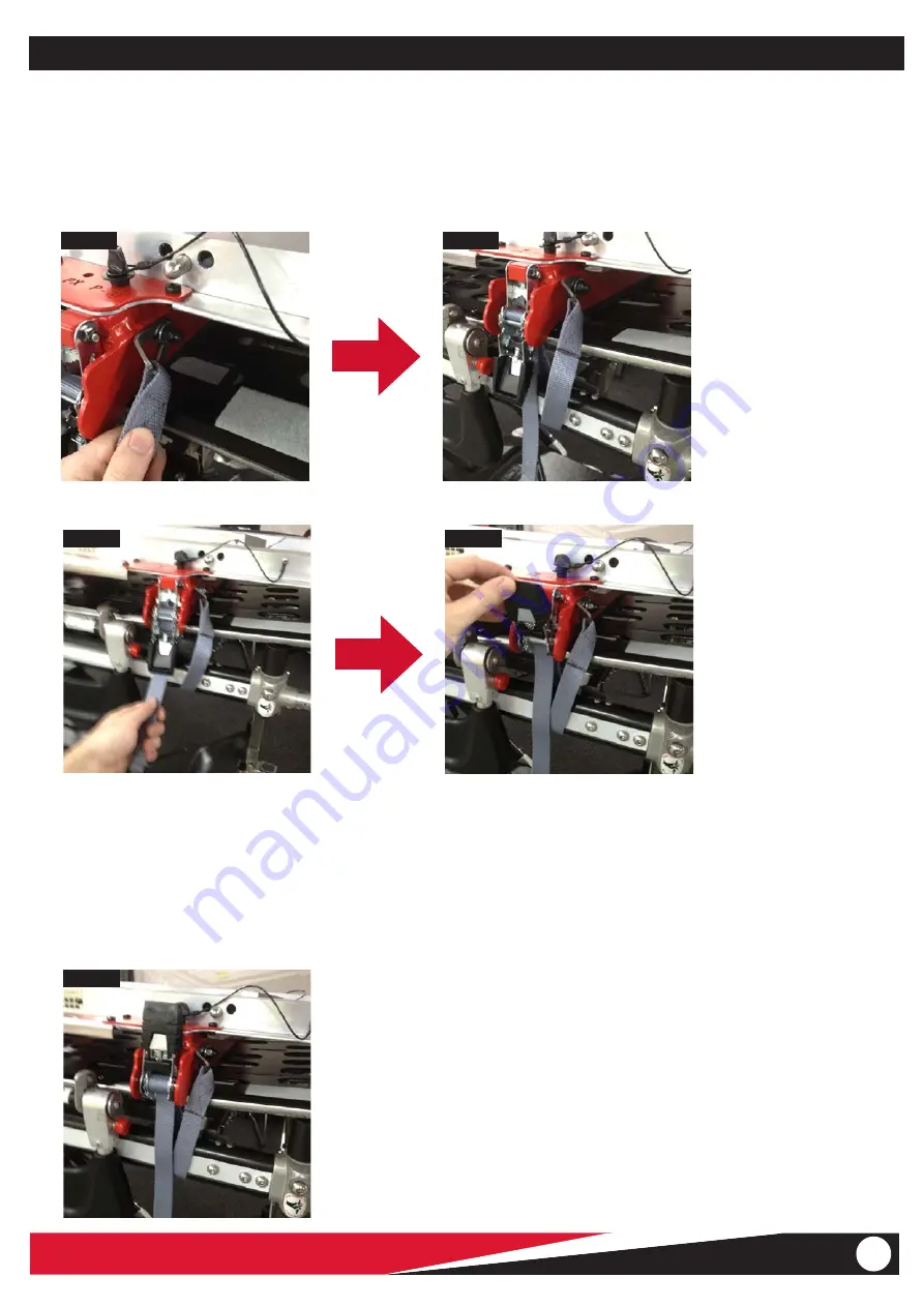
Hook the tang onto one of the two fixing points on the UNI-ClipDoc fixing-bar. 

Pull on the loose end of the  strap to take up the slack.

NOTE: TO PREVENT MALFUNCTION OF THE RATCHET MECHANISM ENSURE THE SLACK IS 

PULLED OUT OF THE STRAP AS SHOWN IN FIG 7 BEFORE RATCHETING THE LEVER. 

Begin ratcheting the lever to tighten the strap. Do not tighten fully at this stage.
Repeat the above on all four ratchet straps.
When all ratchet straps are moderately tight, go around and fully tighten all four ratchets to 

complete the installation. 

5.0 - OPERATION

UNI-ClipDoc

FIG 5

FIG 6

FIG 7

FIG 8

FIG 9

NOTE: ENSURE ALL FOUR RATCHET HANDLES ARE IN 

THE VERTICAL, LOCKED, POSITION BEFORE USE
The Uni-ClipDoc is now ready for use.

Summary of Contents for UNI-ClipDoc

Page 1: ...Users Manual FERNO MAN 0721 220 R2 UK Stock Code 2003 0150 Read this Manual and Retain for Future Reference UNI ClipDoc...

Page 2: ...r should be within and under consideration of applicable regulations and local protocol Training on the proper use of this product must be provided before using this product in an actual situation Ret...

Page 3: ...____________ 8 4 3 UNI ClipDoc Components and Storage____________ 9 5 Operation of UNI ClipDoc _________________________ 10 5 1 Daily checks________________________________ 10 5 2 Assembly of the UNI...

Page 4: ...the safe working loads of any Trolley used with the UNI ClipDoc 1 4 Trolley and Lock Compatibility in conjunction with UNI ClipDoc UNI ClipDoc has been dynamically crash tested and certified to BS EN...

Page 5: ...worn or damaged labels immediately New labels are available from your distributor 1 6 Symbol Glossary The symbols defined below are used on the trolley and or in this user manual Ferno uses symbols re...

Page 6: ...dling procedures 2 2 Training Operator trainees need to Have followed a training plan Read and understand the instructions in this manual Practice using the fully equipped equipment with weight and un...

Page 7: ...PowerPro TL The second fixing bracket set incorporates a clamping mechanism which allows the UNI ClipDoc to be clamped to the integral siderail interface on both PowerX and iNX trolleys providing a s...

Page 8: ...rs 585 mm Overall depth Max over clamp bars 205 mm Overall weight full kit including carry bags 32 3 kg not including optional bridging plate Load capacity Refer to SWL of trolley 4 2 Serial number lo...

Page 9: ...d according to the instructions above to avoid parts going missing or getting mixed up with other UNI ClipDoc units Each UNI ClipDoc half section has its own storage bag The serial number of each sect...

Page 10: ...sert the black spigots into the sockets on the foot end section Keeping fingers clear push down on the head end section to ensure the pegs are fully inserted and no gap exists between the two sections...

Page 11: ...ley the clip on spacer marked PowerX should be installed on both the head end and foot end fixing bars To install the clip on spacers align the three pegs with the sockets and push down into place To...

Page 12: ...es until they click into the locked position The Uni ClipDoc is now ready for use UNI ClipDoc FIG 1 FIG 2 FIG 3 FIG 4 5 5 Installation using the ratcheting fixing bars With the ratcheting fixing bars...

Page 13: ...MALFUNCTION OF THE RATCHET MECHANISM ENSURE THE SLACK IS PULLED OUT OF THE STRAP AS SHOWN IN FIG 7 BEFORE RATCHETING THE LEVER Begin ratcheting the lever to tighten the strap Do not tighten fully at t...

Page 14: ...of the strap just below the tang as shown above and pull firmly to release the tension The tang can then be removed from the fixing point The strap can be left hanging freely as the Uni ClipDoc is lif...

Page 15: ...ow These in turn will force the jammed pins of the Incubator Aero Sled clear of the location blocks so the unit can be removed from the UNI ClipDoc 5 8 Manual stop pins if fitted As a safety precautio...

Page 16: ...he United Kingdom to order parts or for professional repair contact Ferno UK the only agent authorised by Ferno UK to manage service and repair Ferno products elephone Main Reception 44 0 1274 851999...

Page 17: ...infectant Follow the disinfectant manufacturer s instructions for application method and contact time Ferno recommends you inspect the trolley for damage as you clean and disinfect it 1 Remove the mat...

Page 18: ...owered trolleys check that the battery is fitted to the trolley and that it is fully charged at the beginning of each shift ______________________________________________________________________ Press...

Reviews: