Ferm
9
Connect a dust extraction device
Whenever there are facilities for fitting a dust or fume
extraction system, make sure it is connected and used.
Use recommended accessories
The use of any other accessory or attachment other than
recommended in the instructions or catalogue may pre-
sent a risk of personal injury. Use extension cables suita-
ble for the power input of the saw (minimum cable size
1.5mm2). When using a cable reel unwind the cable fully.
BEFORE USING THE JOINTER
Ensure the machine is switched OFF and unplugged
from mains before changing parts or accessories,
adjusting or inspecting this machine.
CHANGING/FITTING SAW BLADES
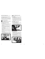
Refer to illustration below
-
Loosen the Allen screw (16) with the 4mm wrench
supplied and open the top of the base plate.
-
Press the spindle lock button and turn the spindle
(17) until it locks. Keep the spindle lock button
depressed.
-
Remove the flange nut (18) anticlockwise and the saw
blade (if fitted) using the wrench (19) supplied.
-
Make sure the flange washer is the right way up to suit
the new blade - one side is for 20mm bore blades and
the other is for 22mm.
-
Check that the lugs on the flange washer engage with
the flats on the spindle.
-
Check the saw blade is on the right way up - cutting
edge of the teeth should follow the arrow marked on
the saw base.
-
Put the new saw blade (20) onto the flange washer
then tighten the flange nut securely clockwise with
the wrench.
-
Release the spindle lock button and check the spindle
is free by rotating it.
-
Close the top of the base plate, and screw in the Allen
screw with washer attached, making sure the washer
is located over the domed part on the saw base. Tigh-
ten securely with the Allen wrench.
CHECKING THE MAXIMUM CUTTING
DEPTH
After changing/fitting a saw blade always check the maxi-
mum cutting depth.
Refer to illustration below.
-
Check that the motor body (15) is back as far as possible.
-
Set the adjustment knob (7) to the ‘MAX’ position
-
Hold the saw base and move the motor body for-
wards until the pin (A) enters the notch in the knob.
-
Turn the saw blade so a tooth tip is on the centreline.
-
Measure the distance between the tip of the saw
tooth and the side of the saw base. The maximum
measurement is 18mm, if it isn’t you will need to set
the cutting depth.
SETTING THE CUTTING DEPTH
-
Move the motor body (15) backwards as for as it will go.
-
Loosen pin (A) and its lock nut.
-
Check knob (7) is set to ‘MAX’ position.
-
Set the cutting depth by checking the distance and
turning the pin as required. When the distance is cor-
rect, lock the pin with its lock nut and tighten.
ADJUSTING THE HEIGHT
Refer to illustration below.
-
Set the height by unlocking the clamping lever (9) (turn
anticlockwise), and turning the height adjustment
knob (10) to set the required height on scale (11).
-
The correct height is half the thickness of the work-
piece – the groove for the biscuit dowel should be in
the middle of the workpiece.
-
After you have set the height, securely lock the lever
by turning clockwise, if the lever is in the way in that
position, pull it outwards and rotate to a better posi-
tion without unscrewing the adjustment clamp.
20
9
11
10
7
15
A
19
18
21
20
17
16
4
Ferm


