


Installation & Operating Instructions
ııııııııııııııııııııııııııııııııııııııııııııııııııııııııııııııııııııııııııııııııııııııııııııııııııııııııııııııııııııııııııııııııııııııııııııııııııııııııııııııııııııııııııııııııııııııııııııııııııııııııııııııııııııııııııııııııııııı
Page 9
www.fptgroup.com
Fenner is a registered trademark of J.H. Fenner & Co. Limited
ııııııııııııııııııııııııııııııııııııııııııııııııııııııııııııııııııııııııııııııııııııııııııııııııııııııııııııııııııııııııııııııııııııııııııııııııııııııııııııııııııııııııııııııııııııııııııııııııııııııııııııııııııııııııııııııııııııı
Page 8
www.fptgroup.com
Fenner is a registered trademark of J.H. Fenner & Co. Limited
Installation & Operating Instructions
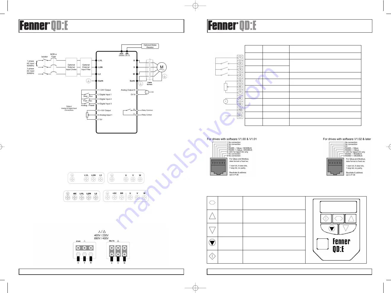
4.3. C
ONNECTION
D
IAGRAM
4.4. D
RIVE AND MOTOR CONNECTIONS
For 1 phase supply power should be connected to L1/L, L2/N.
For 3 phase supplies power should be connected to L1, L2, L3. Phase sequence is not important.
The Motor should be connected to U, V, W
For drives that have a dynamic brake transistor an optional external braking resistor will need be connected to +DC and BR when
required. The brake resistor circuit should be protected by a suitable thermal protection circuit. Further information can be found
in the Advanced User Guide.
The –DC, +DC and BR connections are blanked off by plastic tabs when sent from the factory. The plastic tabs can be removed
if/when required.
Size 1 Connections
Size 2 & 3 Connections
4.5. M
OTOR
T
ERMINAL
B
OX
C
ONNECTIONS
Most general purpose motors are wound for operation on dual voltage supplies. This is indicated on the nameplate of the motor
This operational voltage is normally selected when installing the motor by selecting either STAR or DELTA connection. STAR
always gives the higher of the two voltage ratings.
Typical ratings are:
5.1. C
ONTROL TERMINAL CONNECTIONS
5.2. RJ45 D
ATA
C
ONNECTION
6. O
PERATION
6.1. M
ANAGING THE KEYPAD
The drive is configured and its operation monitored via the keypad and display.
Control Signal
Description
Terminal
1
+24V User Output,
+24V, 100mA.
2
Digital Input 1
Positive logic
“Logic 1” input voltage range: 8V … 30V DC
3
Digital Input 2
“Logic 0” input voltage range: 0V … 4V DC
4
Digital Input 3 /
Digital: 8 to 30V
Analog Input 2
Analog: 0 to 10V, 0 to 20mA or 4 to 20mA
5
+10V User Output
+10V, 10mA, 1k
Ω
minimum
6
Analog Input 1 /
Analog: 0 to 10V, 0 to 20mA or 4 to 20mA
Digital Input 4
Digital: 8 to 30V
7
0V
User ground connected terminal 9
8
Analog Output /
Analog: 0 to 10V, 20mA maximum
Digital Output
Digital: 0 to 24V
9
0V
User ground connected terminal 7
10
Relay Common
11
Relay NO Contact
Contact 250Vac, 6A / 30Vdc, 5A
Default
Connections
For MODBUS RTU register map
information please refer to the
Fenner QD:E Advanced User Guide.
When using MODBUS control the Analog
and Digital Inputs
can be configured as shown in section 8.3
NAVIGATE
UP
DOWN
RESET/
STOP
START
Used to display real-time information, to
access and exit parameter edit mode and to
store parameter changes
Used to increase speed in real-time mode or
to increase parameter values in parameter edit
mode
Used to decrease speed in real-time mode or
to decrease parameter values in parameter
edit mode
Used to reset a tripped drive.
When in Keypad mode is used to Stop a
running drive
When in keypad mode, used to Start a stopped
drive or to reverse the direction of rotation if
bi-directional keypad mode is enabled
Fenner QDE User Guide 9/5/08 9:23 AM Page 9


