


4
F
F
F
F e
e
e
e n
n
n
n d
d
d
d e
e
e
e rr
r
r
®
®
®
®
P
P
P
P a
a
a
a ss
s
s ss
s
s p
p
p
p o
o
o
o rr
r
r tt
t
t
®
®
®
®
P
P
P
P D
D
D
D ––
–
– 5
5
5
5 0
0
0
0 0
0
0
0
Read this manual completely to determine appropriate connec-
tions and switch positions.
•
To Open: release the Safety Latch {A} with your finger tip, then
lift up on Main Latch {B}. Remove both speakers from the tower.
•
To close: position the
speaker on the tower
foot {C} then tilt the
speaker up towards the
tower and close the Main
Latch. The Safety Latch
automatically engages.
Note: Your Passport case
is precision engineered
and careful alignment of
the parts will ensure
easy operation.
The Passport case is
weather resistant in the
closed transport mode.
However, when operating
outdoors, take care to fully protect the Power Tower in the event
of exposure to rain. Remember to allow free air flow through the
front air inlet located at the bottom of the front panel on the
Passport power tower.
Located on the rear of the Passport tower, simply lift the latch
to pull open the door.
If you remove
the micro-
phones and ca-
bles, you will
see a narrow
metal strip lo-
cated on the
back wall of the
storage com-
partment. This protective cover for the optional wireless mic re-
ceiver module connector should only be removed if the module
is to be installed.
Before plugging in, turn both Master Level
controls down to their zero ”0” positions
(fully counterclockwise). Next, make sure
all EQ, Pan and Balance controls are set to
the center notched positions.
Position the speakers so that the cables can
be routed to them safely, and no microphones are aimed into the
speaker. Connect the speakers to the appropriate Speaker Out-
puts on the rear of the Passport using the provided cables. Plug
in all sources, such as microphones, tape decks, keyboards, to
the Passport Inputs. After all connections are made, adjust the
volume up from 0 as described in the Setting Levels section.
NOTE: Plug all sound system equipment into the same outlet or
power strip to enhance system safety and performance. TIP: If
you have other powered equipment connected to the Passport,
it is important to switch the Passport ON last when setting up and
then OFF first when finished to prevent harmful popping sounds
from the Passport speakers each time something is switched on
or off. Switch the Power Switch to the ON position. The Power
LED should illuminate GREEN, if not, see TROUBLESHOOTING at
the end of this section.
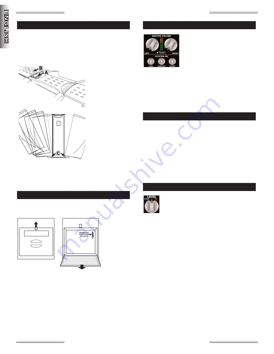
To set system volume and operating levels, it is help-
ful to have an assistant in the audience area checking
levels to ensure full coverage. Slowly rotate the large
Left and Right Master volume controls up to the posi-
tion at “5.” Use a microphone (or other source) in the same po-
sition as it will be used on stage and in the same manner in which
it will be used for the event. Start out with Feedback Killer
™
off,
then slowly turn up the channel input level control to the desired
level (see Peak Indicator section on the next page). Be ready to
quickly turn down the level if you hear the onset of feedback or
“howling.” Some environments may require that you engage Feed-
back Killer
™
to obtain the desired volume level. Repeat this for
each input channel. Once each channel level has been set, you
can adjust the volume of all channels together using the Left and
Right Master Volume controls.
Considering the application and needs of the event, set the sys-
tem EQ controls and select digital effects as appropriate. This is
best achieved by playing recorded material of the same type as
your performance and then adjusting levels to accommodate your
performance and the space.
S
S
E
E
T
T
T
T
I
I
N
N
G
G
L
L
E
E
V
V
E
E
L
L
S
S
P
P
O
O
W
W
E
E
R
R
O
O
N
N
C
C
O
O
N
N
N
N
E
E
C
C
T
T
I
I
O
O
N
N
S
S
M
M
I
I
C
C
&
&
C
C
A
A
B
B
L
L
E
E
S
S
T
T
O
O
R
R
A
A
G
G
E
E
G
G
E
E
T
T
T
T
I
I
N
N
G
G
S
S
T
T
A
A
R
R
T
T
E
E
D
D
Summary of Contents for PASSPORT PD-500
Page 1: ......


