background image

F-900 Instruction Manual 8/14/2017 

1554 NE 3

rd

 Ave, Camas, WA 98607, USA Phone: (360) 833-8835 

15 

www.felixinstruments.com


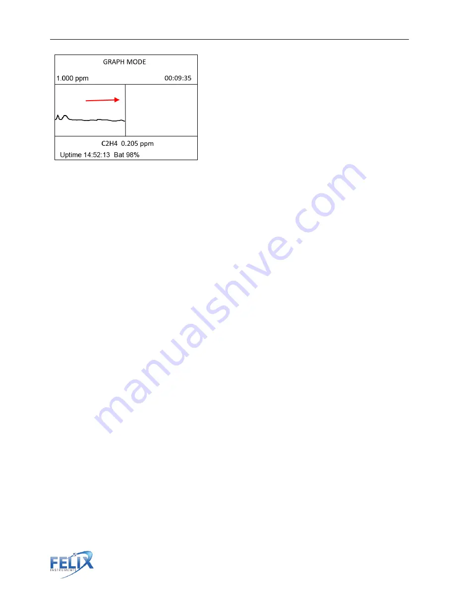
Figure 10: Graph Mode with red arrow indicating direction of movement. 

Directly below the graph is the current ethylene value. Above the graph is the dynamic range 
(on the left it is 1.000 ppm, on the right it is 2.000 ppm). The y-axis scale is set by the highest 
value shown in the buffer. This range will scale vertically, dependent on the highest 
concentration of ethylene measured. If the concentration is small, the dynamic range will reflect 
this. For example, the initial value was 0.162 ppm and there is a sudden peak to 7.578 ppm. As 
the spike or peak occurs, the graph will scale to 10.000 ppm. If the sample returns to 0.168 
ppm, the scale will remain at 10.000 ppm until the graph and the buffer are cleared.   

The scale of the graph can be increased or decreased by using the up and down arrows. 
Pressing the up arrow will zoom in on the data, minimizing the visible range. Using the down 
key will increase the scale, up to 200 ppm. Note that the minimum range of data visible (down to 
0.150 ppm) depends on the current data being graphed. For example, if the current data is 
3.486 ppm, the user may use the up key to zoom in to the 5 ppm range, but cannot zoom in to a 
narrower 2 ppm range. 

The graph begins on the left side and moves with the vertical line towards the right as more data 
points are added. Once the time line reaches the right side of the display, the data will be 
compressed to the far left.  

The time scale relates directly to the vertical position line. In other words, the line moves to the 
right as new data points are added. Every time a data point is added, the time scale is 
incremented. For time under 10 minutes, the graph is updating almost every second. The 
bottom of the display shows the uptime of the F-900 and current battery level.  

Monitor Mode 

The large bold value on the top line is the digitally filtered value of the raw 

ethylene


measurements. Next, the relative 

humidity

 in percent, of the gas stream in the instrument is 

displayed followed by the 

temperature

 in degrees Celsius. The atmospheric 

pressure

, is 

displayed. Press the down arrow to view the 

flow

 rate in milliliters per minute. The default flow 

rate is 80 mL per minute. If the unit has a high resolution CO

2

 sensor on board, the CO

2

 value in 

ppm will be displayed below the ethylene value. If the unit has a low resolution CO

2

 sensor, or 

O

2

 sensor on board, the value will be displayed in percentage (%).  

Summary of Contents for F-900

Page 1: ...vice may not cause harmful interference and 2 this device must accept any interference received including interference that may cause undesired operation Complies With 89 336 EEC Electromagnetic Compa...

Page 2: ......

Page 3: ...r and Battery Power 13 Measure Menu Taking a Measurement 14 Sensor Stability 14 Graph Mode 14 Monitor Mode 15 Measurement Settings 17 Notes About Measurements with the F 900 17 Electrochemical Sensor...

Page 4: ...Automatically Set Zero Offset Correction 34 F 900 Menu System Diagram 36 Setup Menu 37 Setup Measure 37 Setup Autosave 37 Setup Sensor 38 Setup Calibration 39 C2H4 Calibration 39 Offset Correction 40...

Page 5: ...g 77 Method 2 Sampling with Filtration Trapping 77 Method 3 Long Term Monitoring with Filtration 78 APPENDIX II Guidelines for Measuring Sample Bags 79 To Collect a Sample Using a Sample Bag 79 Analyz...

Page 6: ...ailable only through elaborate and expensive gas sampling and gas chromatography analysis The intent of the F 900 s portable design is to aid the research community in developing real world ethylene m...

Page 7: ...monitoring in the field Multiple configurations to accommodate in situ research and controlled atmosphere monitoring Instantaneous and accumulated measurement modes Monitor and Graph View Quick conne...

Page 8: ...80 mL min Measuring Rate 1 second intervals open or closed loop Warm up time 1 minute C2H4 PPB Sensor Electrochemical Nominal Range 0 10 ppm Resolution 0 001 ppm Lower Detection Limit 0 025 ppm 25 pp...

Page 9: ...ter Warm up time 3 minutes Weight 172 6 g Offset Recalibration Weekly Span Recalibration 6 months calibration gas required CO2 Percent Sensor Infrared Sensor Pyroelectric detector Nominal Range 0 20 R...

Page 10: ...evel is too low or if the inlet and outlet gas connections are blocked while the pump operates This can cause false readings or irreparable damage to the sensor Use a T valve when connecting the F 900...

Page 11: ...orking electrode R reference electrode C counter electrode E electrolyte Image credit doi 10 1093 aob mcs259 The F 900 flow rate is regulated by a pump and a flow meter Additional optional sensors are...

Page 12: ...ts a complex mixture of hydrocarbons including ethylene Oxidation of these other gases in the electrochemical sensor cannot be readily distinguished from ethylene This causes the ethylene value to be...

Page 13: ...t filter when measuring a gas mixture or interfering gases present will be reported by the instrument Alcohols can induce a baseline shift and or change the sensitivity of the ethylene sensor To recov...

Page 14: ...part of the tubing accessory kit Male and female quick connectors can be added to tubing and used to connect sample bags or custom chambers to the F 900 Figure 6 Accessories and parts that arrive with...

Page 15: ...ample fruit or plants The fruit chamber includes a closed chamber lid and a lid with a seal to allow sampling of fruit still intact on the plant The F 900RK includes all the parts and accessories that...

Page 16: ...tery life remaining will be displayed on the bottom line The uptime or time the instrument has been powered on is displayed in hours minutes followed by the battery life in percent Note If the F 900 d...

Page 17: ...will flash powering off on the top line when you hit the power key For fastest charging of the F 900 use the highest rated port on the charger and do not connect any other USB devices to the charger...

Page 18: ...CO2 PCT sensor is from 0 20 and does not have the same power draw To turn off on the CO2 PPM sensor 1 Go to Setup Sensor Sensor Selection 2 When asked Are you sure you want to continue press Enter 3...

Page 19: ...display will show the file that is open and the flow of gas being pumped through the instrument Below this will be whether the initialization is automatic or manual If the initialization is automatic...

Page 20: ...hed For example if the current data is 3 486 ppm the user may use the up key to zoom in to the 5 ppm range but cannot zoom in to a narrower 2 ppm range The graph begins on the left side and moves with...

Page 21: ...en 4 5O C above ambient and in turn relative humidity readings are affected The use of water in Chamber In PolarCept see page 8 will also affect relative humidity readings The detection rate Det Rate...

Page 22: ...s changed The Set Zero procedure begins by automatically closing the IN and OUT port valves on the front of the instrument Closed Loop and enabling Chamber Out On with KMnO4 The instrument will contin...

Page 23: ...d not covered If connected to tubing or a fruit chamber disconnect and reconnect the tubing from the IN port If using water in Chamber In remove the top panel of the F 900 and ensure no water has ente...

Page 24: ...in Chamber Out and it should be turned on Possible reasons to condition the air returning to the fruit chamber include scrubbing humidity with silica gel or scrubbing CO2 with soda lime Build up of c...

Page 25: ...900 Instruction Manual 8 14 2017 1554 NE 3rd Ave Camas WA 98607 USA Phone 360 833 8835 20 www felixinstruments com Observe and record the rate of change of ethylene over time with the F 900 Monitor Mo...

Page 26: ...Gas Chromatograph GC No need for N2 H2 or bottled air Portable No heating or oven required Predicts ethylene concentration without chromatography Figure 13 GC Emulation port connected to front of inst...

Page 27: ...ult GC Emulation Mode Tips In general higher injection volume will also increase signal detection Recommended minimum injection volume is 5 ml The F 900 requires about 5 10 minutes of warm up time whe...

Page 28: ...Injection port setup 3 Wait for the instrument to stabilize 4 Set parameter then press Enter 5 Inject the gas sample then press Enter Stabilizing environment Enter Skip C2H4 x xxxppm Humidity Temperat...

Page 29: ...ments com Figure 15 Injection of gas sample 6 Wait while the sample is processing 140 seconds 7 View the results Enter to repeat for another sample or Stop to exit Figure 16 Proper technique for filli...

Page 30: ...he first step is obtaining an offset point the zero point and second step is obtaining a span point Lastly it is good practice to verify the calibration using another standard gas See Table 1 for a su...

Page 31: ...egulator the gas is drawn out of the regulator cylinder by the pump of the F 900 When the regulator is fully twisted onto the cylinder the PSI on the gauge will move Rotate the regulator until it is t...

Page 32: ...ghlighted 2 Options for calibration parameters and recalibration can be seen Select Re Calibration Note Changes to any of the calibration parameters should be performed under the supervision of a Feli...

Page 33: ...tting offset using the KMnO4 in Chamber out and will give a countdown to completion Zero calibration takes the instrument around 15 20 minutes to complete 6 Once offset has been set the F 900 will imm...

Page 34: ...ndard gas to set zero Please see page 29 An alternate method exits for setting zero with the use of Soda Lime and is described below 1 Select the re calibration function for the CO2 ppm sensor 2 The d...

Page 35: ...0 Use extra tubing to get the intake source away from human breath Use a buffer tank system to stabilize the intake source 1 Find and clean an empty bottle with cap which is at least 3L in volume 2 Dr...

Page 36: ...6 Connect the in tubing to the intake port on the instrument 7 To use the buffer bottle make sure that the tubing is clear from obstruction Connect the In tubing to the unit Place the buffer bottle i...

Page 37: ...PM CO2 PCT Please follow the Standard Operating Procedure on page 29 and refer to Table 1 on page 27 to calibrate this sensor The firmware supports a 3 point calibration for this particular sensor for...

Page 38: ...following steps If using PolarCept it is recommended that the set zero process be completed with Chamber IN enabled The DI water used for PolarCept can introduce additional impurities Setting zero wi...

Page 39: ...and Closed Loop On Off Figure 20 Measurement Settings Menu display left flow path of internal gas stream right Manually Set Zero PolarCept Enabled To perform an offset with PolarCept enabled first fol...

Page 40: ...default 30 minutes and happens during Sensor Stability the first screen when measurement mode is initiated The default interval between offset corrections is 24 hours for continuous use or during the...

Page 41: ...ity Graph View Monitor View Settings Setup Measure GC Emulation Monitor Autosave Sensor Sensor Selection Calibration C2H4 PPB Calibration Parameters Re calibration PPM Calibration Parameters Re calibr...

Page 42: ...search Kit and requires the use of the inline injection port with septum To save changes in the Setup Measure menu press Save Use the up and down arrows to toggle between options Setup Autosave To sel...

Page 43: ...measurement will toggle Autosave to off To avoid changing any configuration press the Stop key to exit back to the Setup Menu Setup Sensor The Setup Sensor Menu has Sensor Selection Sensor Selection a...

Page 44: ...alibration Menu Press Enter to confirm and get into the menu The options at the Setup Calibration menu are C2H4 CO2 O2 system DAC flow and injection parameters C2H4 Calibration Re calibration or chang...

Page 45: ...or upon startup if more than 24 hours have passed between uses The offset will be corrected when the user first enters measurement mode and is in the Sensor Stability screen To enable the automatic o...

Page 46: ...e appropriate shift in time and press Save Setup Flow The air flow of the F 900 is an important factor for taking good measurements The default flow rate is 80 ml min Flow rate is adjustable from 80 2...

Page 47: ...itioning chamber is seated properly when screwing it on the F 900 The purpose of the inbound chamber Chamber In is to condition the air before it reaches the sensor Chamber In additionally provides a...

Page 48: ...is necessary To use Chamber Out to condition the air replenishing the fruit chamber enable Chamber Out in the Setup Chamber menu and fill Chamber Out with the appropriate consumable Connect the fruit...

Page 49: ...In with distilled water to max fill line located on back of F 900 This mode may not be applicable at high ethylene concentrations When the F 900 is using the water to filter out alcohol the water must...

Page 50: ...bic filters in line with the internal tubing This is to protect the F 900 in case any water is sucked into the instrument when using PolarCept To avoid drawing water into the internal tubing of the F...

Page 51: ...developed for using the F 900 with other external advanced control systems When this mode is not being used set to DISABLE o Note if Setup Chamber Chamber In is currently set to Special enabling CNTL...

Page 52: ...r 0 max C2H4 range 20ppm or 200ppm 9 Analog Input reserved 10 Analog control input for cleaning use with CONTL_IN enabled The digital outputs 4 5 and 6 can sink up to 45mA to drive an optocoupler They...

Page 53: ...33 8835 48 www felixinstruments com for calculated concentrations displayed on the F 900 Those concentrations are then updated every 200 milliseconds to a DAC output on the terminal block for CO2 and...

Page 54: ...ight contains the file size The options are use the up or down arrow keys to scroll through the files press the left arrow or Stop to exit to the View Menu Note A file with a negative number for the f...

Page 55: ...ly The Charge will read off when no charger is plugged in and Complete when finished charging The Board refers to the hardware version of the unit Features described in this manual are associated with...

Page 56: ...PS menu and is synchronized with minute and second alignment Often when the instrument is turned on indoors the latitude longitude and altitude will be blank This occurs when no satellite signal can b...

Page 57: ...he file name or set up This feature is useful if it is necessary to do a number of similar measurements The user can take these measurements to a particular file copy the results clear the file and be...

Page 58: ...d in a number or else the file will be corrupt and no data will be saved to it Pressing the Save key in the Create mode saves the file Should the file name be identical to another file name the instru...

Page 59: ...the screen if the file was opened successfully Press Stop or the left arrow to go back to the File Menu Moving the cursor to another file after opening a file and then exiting the menu by pressing eit...

Page 60: ...instrument and the computer while performing measurements If the user tries to operate the instrument through the computer the files are subject to becoming out of sync breaking alignment and causing...

Page 61: ...computer before making changes or starting analysis Below is an example of ethylene data plotted for PolarCept that shows the typical peaks and valleys for the measure cleaning cycle At the end of the...

Page 62: ...Check It Gas Analyzer which can be similarly applied to other Felix Instruments products 1 Install FlashAir Wi Fi card software appropriate to the SD card a Visit https www toshiba co jp p media engl...

Page 63: ...images stored on the FlashAir card can be viewed and the internet can also be accessed This is convenient when for example uploading image files downloaded form a FlashAir card onto social networking...

Page 64: ...the internet access point password Enter the password for the access point that you will use o In your browser enter http flashair to view or stream your files For more information on the Toshiba Fla...

Page 65: ...software Always double check the webpage for the latest compatible firmware version depending on the serial number of the F 900 Please contact Felix Instruments technical support with questions about...

Page 66: ...er to proceed installing libusb driver This could take up to 1 minute to complete Note Wait for Windows obtaining driver process to complete before clicking Install driver When the device drivers and...

Page 67: ...ctions in the software to hold down the Power button 7 Release the Power button when instructed 8 Wait for the flash to be erased and then written When the firmware transfer is complete the software w...

Page 68: ...Phone 360 833 8835 63 www felixinstruments com 3 Connect the device to computer via USB and repeat the download firmware procedure After the firmware update is successful it is recommended to let the...

Page 69: ...p exe from https felixinstruments com support F 900 software B Install C Launch the downloaded G A S program Connection to the GAS software is available through USB cable connection 1 The searching bu...

Page 70: ...e The Control Panel menu displays toggle keys and a simulated device screen which allow the user remote control of the F 900 The Calibration menu navigates the user through the calibration process for...

Page 71: ...but the graphic display switches the CO2 and O2 concentrations See the Control Panel section below for more information on the simulated device screen Another known bug is if the monitored F 900 has a...

Page 72: ...int calibration process for the F 900 Including Zero Calibration and Span Calibration The set zero process will require known standard gas of 100 Nitrogen N2 gas to set a zero baseline Next the user w...

Page 73: ...tically initiate a continuous measurement to run the standardized tests on the sensors Checking Sensor Signals will check each of the raw sensor signals on your device Each of these values are tested...

Page 74: ...still not fall within the reported accuracy range of the specified sensor This means that even if a sensor passes this diagnostic it may need calibration depending on the accuracy desired The final au...

Page 75: ...ted in your country Felix Instruments is committed to providing customers with high quality timely technical support Technical support representatives are there to answer your technical questions by p...

Page 76: ...see moisture develop in the tubing when monitoring a fruit in the chamber a There is a protective hydrophobic filter inside the IN port on the front of the F 900 This will prevent moisture from fully...

Page 77: ...the file name is a negative number this indicates an error You should delete the file and create it again Then open it and check that the value is zero Now you can save data into this file 6 What cons...

Page 78: ...runs out of water a If the cell runs out of water the lead electrode could undergo sulfation This would affect the sensitivity by reducing the active area on the lead electrodes It is more likely tha...

Page 79: ...ty measured a The temperature and relative humidity sensors are located inside the F 900 before the electrochemical sensor There is an additional relative humidity sensor after the ethylene sensor to...

Page 80: ...t methods for detecting ethylene in plants Annals of Botany 2012 DOI 10 1093 aob mcs259 Golding J Shearer D McGlasson W Wyllie S Relationships between Respiration Ethylene and Aroma Production in Ripe...

Page 81: ...harvest Responses of Malindi Cavendish Banana to Various Storage Conditions International Journal of Fruit Science volume 13 4 p 373 2013 DOI 10 1080 15538362 2013 748378 Pech J Bouzayen M Latche A Cl...

Page 82: ...00 5 After sampling the headspace for 5 minutes or a set period of time of your choosing take a syringe sample and run it in the GC gas chromatograph Record result in spreadsheet program such as Micro...

Page 83: ...the method and how to realize if the cleaning period should be extended Procedure 1 Fill conditioning Chamber In with distilled water and clean the water using potassium permanganate in an in line col...

Page 84: ...value when opening closing by holding side stem while turning entire upper portion of fitting one revolution Store bags flat Do not roll or crease bags during storage Do not use bags at temperatures a...

Page 85: ...ndle or hanging device Although it is durable it is not intended for these uses Analyzing a Sample Bag with the F 900 Connect the sample bag to the IN port of the F 900 Open the sample bag to allow ga...

Page 86: ...APPENDIX III 8L Chamber Accessory These visuals supply the user with the basic Do s and Don ts of working with the 8L Chamber accessory Designed for measuring samples in a closed system the 8L chambe...

Page 87: ...for the 0 20 range When recalibrating the CO2 PCT sensor choose the expected or desired range and calibrate with the recommended concentration If using the 0 100 CO2 range values above 20 are extrapo...

Page 88: ...a measurement Press the right arrow again to skip the sensor stabilization a There is a short lag in the F 900 Controller software as it pulls data from the F 900 instrument This lag interval is adju...

Page 89: ...andard gas is connected The data should be trending towards the expected concentration and begin to stabilize 9 Wait at least 7 minutes once the signal has stabilized and does not change more than 40...

Page 90: ...00 Instruction Manual 8 14 2017 1554 NE 3rd Ave Camas WA 98607 USA Phone 360 833 8835 85 www felixinstruments com 11 Disconnect the calibration gas and watch the data trend toward ambient ethylene lev...

Page 91: ...r regulators are acceptable just use a T junction when connecting to the instrument to protect the instrument from damage 3 Determination of the size of tank to order Consider how many calibrations ca...

Page 92: ...Ethylene C2H4 in air Part number 103DSxxxC2H4A xxx ppm concentration 2 5 10 20 75 100 or 500 ppm CO2 balance Nitrogen Part Number 103DSxxxxCO2N xxxx ppm concentration 1 000ppm or 2 000ppm Part Number...

Page 93: ...Sensors Included Yes No C02 PPM CO2 PCT O2 PCT CALIBRATION PARAMETERS C2H4 PPB C2H4 PPM Internal offset Internal gain Calibration RH Calibration T RH slope RH offset T slope T offset Optional Sensors...

Page 94: ...is not manufactured by Felix Instruments is to be covered only by the warranty of its manufacturer Felix Instruments will not be liable to the Buyer for loss damage or injury to persons or to property...

Reviews: