12
ENGLISH
5.6 VERTICAL PLANE LIMIT STOP ADJUSTMENT
(0° - -45°) (fig.21)
- Lower the head of the machine and lock it with the
special pin.
- Place the turn-table on 0 and lock in position.
- Adjust the head on 45° and position square
A
, as in
fig.21.
- Regulate the 45° by means of screw
B
, after having
loosened the nut.
- Tighten the nut in order to be certain that the position
will remain unchanged.
6
OPERATION AND USE
6.1 CUTTING SPEED
This mitre saw range cuts a wide variety of materials
with an extensive choice of different possible cuts. Given
this, the user must evaluate blade employment according
to the material, cutting speed and blade advance speed.
Some references to the above values are shown in the
table.
BLADE WIDIA
MATERIAL
BLADE DIAM - N° TEETH
CODE
G/MIN
WOOD
Ø 250 mm - Z 24
6554512098
4000
WOOD
Ø 250 mm - Z 60
0000512038
4000
PVC
Ø 250 mm - Z 60
0000512038
4000
ALUMINIUM
Ø 250 mm - Z 60
0000512062
3000
FRAMES
Ø 250 mm - Z 80
0000512085
4000
STEEL
Ø 250 mm - Z 40
0000512095
2000
Ø 32 mm
6537246464
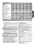
CAUTION: modelsT 777 CE - T 778 CE are equipped with motor speed adjustment. The value given in the table shows
the position of speed selector according to the material to be machined.
6.2 CUTTING WITH THE BLADE AT 90° AND THE
TURN-TABLE ROTATED (fig.4 and fig.5)
- Unlock turn-table A by releasing the knobs
A
(fig. 10).
- Rotate the turn-table, using the handgrip, selecting the
desired angle by means of the graduated scale and
index
B
, then lock knobs
A
once more.
Note: there are prefixed cutting angles (0° ±15° ±22°30'
±30° ±45°) on which the turn-table can be easily locked
(except T770 and T771).
6.3 CUTTING WITH THE BLADE AT AN ANGLE
AND THE TURN-TABLE AT 0° (fig.6)
- Unlock the blade unit by loosening knob
D
(fig. 9).
- Rotate the blade unit selecting the desired angle by
means of graduated scale
C
(fig.10), locking knob
D
once more.
6.4 USING THE MITRE SAW
CAUTION - Make sure that the lock button E (fig. 1) is
disengaged (protruding).
- Raise the upper surface to the maximum height.
- Start with the blade unit in the rest position (raised and
with safety pin inserted).
- Firmly fix the material to be cut to the cutting surface.
CAUTION - When cutting aluminium or steel sections
the use of 6976000000 is indispensable.
- Start the machine and wait until the blade reaches max.
r.p.m.
- Press the blade unit release button.
- Gradually lower the blade unit and perform the cutting
operation.
CAUTION - Pressing on the handgrip stronger will not
reduce cutting time, but may cause reduced efficiency
due to motor overload.
6.5 BLADE START AND STOP
CAUTION - Check that the mobile protection casings
are correctly positioned when the blade is in its rest
position (raised).
The machine is equipped with a release push button
C
(fig. 1) which starts and stops the blade.
It is possible to lock such switch into the “ON” position by
pressing the lock button
E
(fig. 1).
Summary of Contents for T770
Page 3: ...1 2 3 4 5 6 7 G D C E H I A K L M B F F A B C E D...
Page 4: ...13 12 15 14 10 9 8 11 B C A D A B C A B A A B C D B A A A B C...
Page 5: ...21 20 23 22 18 17 16 19 A B A B C B A C A C B A B A B C...
Page 6: ...30 28 25 24 29 A B C 32 31 B A A B A B A B C C C E...
Page 7: ...T 771 T 778 T 770 T 777 T 777 CE T 778 CE...
Page 55: ...48 K FELISATTI elettroutensili S p A...
Page 57: ...50 K...
Page 59: ...52 K...
Page 60: ...53 K...
Page 61: ...54 K...
Page 62: ...55 K...
Page 99: ...T770 Serie 103 400 FELISATTI 03 02 T 771 03 02 FELISATTI...
Page 100: ...T777 Serie 104 500 FELISATTI 03 02 FELISATTI MOTORE T 777 03 02...
Page 101: ...T777CE Serie 400 FELISATTI 03 02 FELISATTI MOTORE T 777 CE 03 02...
Page 102: ...T 778 Serie 104 FELISATTI 03 02 FELISATTI MOTORE T 778 03 02...
Page 103: ...T 778 CE FELISATTI 03 02 FELISATTI MOTORE T 778 CE 03 02...


