background image


- 7 - 

 
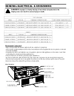
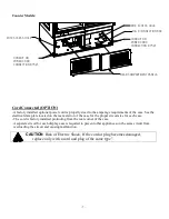
Counter Models: 
 

FIELD CONNECTION BOX

CONDUIT OR

POWER CORD 

CONNECTION .875

O

MISC ACCESS HOLE

MISC ACCESS HOLE

REAR COMPARTMENT PANELS

CONDUIT OR

POWER CORD 

CONNECTION .875

O


Cord Connected (OPTION)  

-A factory installed optional power cord is properly sized to the amperage requirements of the case. See the 
electrical data plate located on the rear exterior of the case for the proper circuit size for each case.  
- The cord is factory installed protruding from the rear corner of the case. 
-A separate circuit for each display case is required to prevent other appliances on the same circuit from 

overloading the circuit and causing malfunction.  


CAUTION  

Risk of Electric Shock. If the cord or plug becomes damaged, 


 replace only with a cord and plug of the same type". 


Summary of Contents for ITD48

Page 1: ...ote Refrigerated Models ITD Non Refrigerated Displays KEEP THIS MANUAL FOR FUTURE REFERENCE Engineering and technical data are subject to change without notice FEDERAL INDUSTRIES 215 FEDERAL AVE Belle...

Page 2: ...Additional Parts 6 Cleaning 6 INSTALLATION INSTRUCTIONS COUNTER MODELS 6 Inspection For Shipping Damage 5 Locating The Display Case 6 Removing Case From Shipping Skid 6 Additional Parts 6 Cleaning 6 C...

Page 3: ...y Cleaning 23 Weekly Cleaning 24 Weekly Exterior Cleaning 26 SERVICE 27 Service Information 28 Pre Service Checklist 28 Electronic Control Operation 16 SALE DISPOSAL 32 Owner Responsibility 32 WIRING...

Page 4: ...omponents contain technical instructions intended only for persons qualified to perform electrical work DANGER Improper or faulty hookup of electrical components in the case can result in severe injur...

Page 5: ...r death will occur if you ignore the message WARNING Severe injury or death can occur if you ignore the message CAUTION Minor injury or damage to your case can occur if you ignore the message NOTICE T...

Page 6: ...MIN CIRCUIT AMPACITY 15 MAX FUSE SIZE 15 Permanent Connected Only a licensed electrician must perform all case electrical connections All electrical wiring hookups must be done in accordance with all...

Page 7: ...ments of the case See the electrical data plate located on the rear exterior of the case for the proper circuit size for each case The cord is factory installed protruding from the rear corner of the...

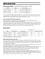
Page 8: ...834R R134A 1 2HP 3750 BTUH 90F 20F 32 0 ITR6026R ITR6034R R134A 1 2HP 3750 BTUH 90F 20F 32 0 Use pressure gauges to set pressure control Remote Refrigeration Operation The remote models are designed t...

Page 9: ...trap must be installed in the suction line at the foot of every riser to insure oil return Dry nitrogen must be used to flow through tubing while brazing refrigeration lines 4 Suction line must be ins...

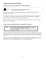
Page 10: ...that the drain trap terminates properly over the water reservoir Condensate Pump Standard Remote optional Self Contained When unit is shipped with a condensate pump a condensate discharge hose is supp...

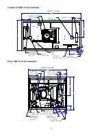
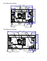
Page 11: ...ECTION BOX ACESS HOLE 2 75O ACESS HOLE 2 75O FILTER DRIER SIGHT GLASS ELECTRICAL CONNECTION 88O 17 3 3 7 9 7 36 30 FRONT TOP VIEW Counter ITR48 Self Contained CONDENSING UNIT CONDENSATE EVAPORATOR OR...

Page 12: ...DRIER SIGHT GLASS ELECTRICAL CONNECTION 88O 60 30 3 7 3 11 5 17 9 9 FRONT TOP VIEW Floor ITR36 Self Contained CONDENSING UNIT CONDENSATE EVAPORATOR OR PUMP POWER SUPPLY ELECTRICAL CONNECTION BOX ACES...

Page 13: ...ECTRICAL CONNECTION 88O FRONT TOP VIEW LEG LEVELER PLATES OR CASTER POCKETS 48 30 8 17 5 9 9 9 2 3 5 12 0 Floor ITR60 Self Contained CONDENSING UNIT CONDENSATE EVAPORATOR OR PUMP POWER SUPPLY ELECTRIC...

Page 14: ...14 Refrigerated Remote Models Counter ITR36 Remote Counter ITR48 Remote...

Page 15: ...15 Counter ITR48 Remote Floor ITR36 Self Remote...

Page 16: ...16 Floor ITR48 Remote Floor ITR60 Remote...

Page 17: ...e or glass breakage will result 1 Remove crate top and sides and note missing or damaged items as explained in the pre installation procedures outlined above 2 Move the case as near as possible to the...

Page 18: ...skid or moving the case Case damage or glass breakage will result 2 Remove crate top and sides and note missing or damaged items as explained in the pre installation procedures outlined above 8 Move...

Page 19: ...s provided The case must be sealed to the counter using a NSF Listed Sealant IMPORTANT When placing cases in a line up the number of end panels used will be different The cut out and hole placement di...

Page 20: ...the number of end panels used will be different The cut out and hole placement dimension will need to be adjusted for each particular line up circumstance See LINE UP INTALLATION section of this manua...

Page 21: ...placed into cabinet remove the 4 handles and install side glass as described in End Panel Installation section of this manual LIFT HANDLES Once case is in place it must be secured to prevent it from...

Page 22: ...e and discharge louvered panels can be moved to front of compartment and the solid panels moved to the back of compartment if air intake and discharge is required out of front of cabinet The Outer Duc...

Page 23: ...ticular line up circumstance See LINE UP INTALLATION section of this manual The condensate air louvers are located on each side of the condensate evaporator compartment Do not block these louvers The...

Page 24: ...anel clears bottom of base and remove from case Front Panel FRONT PANEL SCREWS FRONT PANEL FRONT PANEL SCREWS TOP PANEL RETAINER 1 Disconnect power to Display Case 2 Remove 2 front panel phillips head...

Page 25: ...ith one louver panel in front and one in back to allow front condenser air in or out of front and rear air in or out back This must be determined before placing unit into counter and cabinet must be p...

Page 26: ...ee Case Line Up Installation section of this manual 1 On each side of case there are 3 keyhole mounting slots for easier installation of glass There is 1 mounting hole in the front top corner of case...

Page 27: ...w the instruction in the illustration below Starting with the longest brackets for bottom shelf insert 1 of the 2 shelf brackets in the desired shelf standard slot on one side of the case Place the lo...

Page 28: ...ght must be facing towards back of case Hook shelf support end flanges into front notch of shelf brackets on each side of case 6 Install rear shelf supports with no lights on to shelf brackets All she...

Page 29: ...on Clean area of glass where glass shelf holder is to be located with rubbing alcohol and let air dry before installing shelf glass holder Remove backing from tape located on flat side of glass shelf...

Page 30: ...h the outer door and lift the door upward until the bottom edge of door clears the lower track and then swing the bottom of the door outward and down out of upper track 2 After the outer door is remov...

Page 31: ...H POWER SWITCH Power Switch The unit has a power switch that turns off power to the entire unit including the condensate evaporator and the lights Light Switch The unit has a light switch that turns o...

Page 32: ...on press and hold for approx five seconds The display will read On while the button is depressed When the control powers on the display will read the relative current case temperature on initial star...

Page 33: ...is being held The defrost is initiated when the defrost mode indicator illuminates on the display The control display will then return to reading the case temperature When the defrost mode indicator...

Page 34: ...distributed evenly across the entire shelving area Determine desired shelving location and angle before placing product in case Product must be removed to readjust shelf location and angle Refrigerate...

Page 35: ...OIL BACK PANELS COUNTER ITR MODEL It is very important that the Condenser coil is cleaned twice per month to insure proper refrigeration performance and to prevent compressor failure Failure to clean...

Page 36: ...unit does not have a time clock so the defrost cycles cannot be set for any specific time of day The unit also has an On demand defrost feature that will initiate a defrost when the temperature differ...

Page 37: ...ely read overload or very high in the mega ohm range 3 Ensure that probes are wired per the wiring diagram provided 4 Replace probe if other remedies fail or if probe resistance deviates from Error Re...

Page 38: ...r switch and light switch to off position 3 Remove Shelf from display case 4 Unplug 24v DC power wire from end of existing LED light strip 5 Remove the shelf support with light from case 6 Use a putty...

Page 39: ...ior tilt the front glass forward Tilt the front glass out by grabbing the top edge of glass with finger tips and pulling it away from magnetic strips on case Tilt glass until it stops at about 30 degr...

Page 40: ...rical components with water to prevent electrical damage to the case NOTICE Shut off lights and power switches and remove all product from case Allow sufficient time for the unit to reach room tempera...

Page 41: ...o dry 9 Clean behind front glass hing using warm soapy water and sweeping debris to each end and 10 Clean all foreign material from inner and outer rear door tracks using warm soapy water and a brush...

Page 42: ...e refrigerant charge be evacuated into a recovery system to prevent the possibility of hydrofluorocarbons HFC s from being released into the atmosphere If moisture or liquid is observed around or unde...

Page 43: ...ght strip upside down Case Temperature Too Warm Check that the cold air inlet and outlet slots are not blocked Be sure that the rear doors are closed and tightly sealed Check for a blocked or dirty co...

Page 44: ...customer service department at Federal Industries at 800 356 4206 The customer service department at Federal Industries should be contacted at the time of sale or disposal of your case so records may...

Page 45: ...L 120V 1PH 60HZ DARK LINES REPRESENT CONDUCTOR CORD ITR SELF CONTAINED MODELS 91 20568 4 25 16 Y W W 4 5 9 6 7 10 8 R TEMP PROBE DEFROST PROBE SHELF LIGHT W 24V POWER SUPPLY 2 FANS 5 ONLY RIB LIGHT QU...

Page 46: ...H RIB RIB RIB TOP LIGHT CONDENSATE PUMP OR EVAPORATOR G Y B BRW RIB RIB RIB RIB B R B R BLK RIB BLK RIB BLK BLK M PLUG BLK RIB BLK SHELF LIGHT SHELF LIGHT BLK BLK BLK W BLK G Y BLK RIB BLK C BLK W R B...

Page 47: ...20472 2 50 20471 L 50 20471 R 50 20471 1LA 50 20471 1RA 64 20476 2 64 20476 4 ITR6034 50 20471 3 50 20472 3 50 20471 L 50 20471 R 50 20471 1LA 50 20471 1RA 64 20476 3 64 20476 4 REFRIGERATION COMPONE...

Reviews: