


18
Installation and Maintenance Instructions
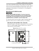
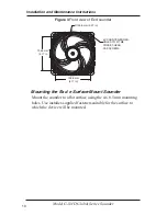
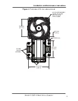
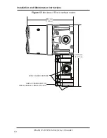
Model G-SND Global Series Sounder
b.
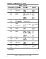
Set the tone selector switch to
0
.
c.
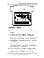
Connect the line (hot) power source wire to the
terminal block position marked
L1
on the PCB.
d.
Connect the neutral (common) power source wire to
the terminal block position marked
L2
on the PCB.
e.
Connect the ground wire to the terminal block
position marked
EARTH
.
f.
Connect the common wire from remote switching device
to the terminal block position marked
SEL
.
g.
Connect the tone select wires from remote switching
device to the terminal block positions marked
T1
,
T2
,
T3
, and
T4
.
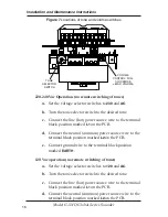
24 Vdc operation (remote switching of tones with local power)
a.
Set the voltage selector switches to
230
and
DC
.
b.
Set the tone selector switch to
0
.
c.
Connect the negative (
–
) power source wire to the
terminal block position marked
L2
on the PCB.
d.
Connect the positive (
+
) power source wire to the
terminal block position marked
L1
on the PCB.
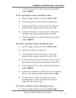
e.
Connect the ground wire to the terminal block
position marked
EARTH
.
f.
Connect common wire from remote switching device
to the terminal block position marked
SEL
.
g.
Connect tone select wires from remote switching
device to the terminal block positions marked
T1
,
T2
,
T3
, and
T4
.
For 24 Vdc operation (remote switching of tones with
remote power)


