FEC Remote Lighting Controller V4 HP0832
User Installation and Operation Manual
© Interleader Ltd 2020
44 of 64
26/08/2020
9.6 Electrical Installation
It is recommended that mains cables are fixed first to avoid damage to aerial or signal cables.
If the FEC RLC is to be operated from a mains power supply it must be connected to the supply
using a fused double pole isolator.
The controller has a maximum power consumption of 30watts so if the supply is only powering the
controller (the switched circuits being separate) then a 5 Amp fuse should be used.
If the same supply is to be used both to power the controller and the switched circuits then the
cable, switch and fuse rating need to be sized accordingly.
WARNING
– If the circuits to be switched are fed from a separate isolator it is imperative that this
is also isolated before work is commenced.
9.7 Circuit Connectors and Cable Entry (V4 enclosure)
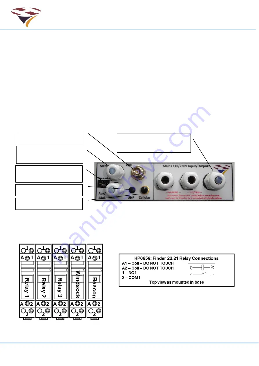
The Picture below shows the connectors and cable entry arrangements on the bottom of the base
for RLC V3 units
9.8 Relays
Three 20 Amp Finder type 22.21 relays are fitted to the controller. Each has 1 Normally Open
(NO) contact set as shown in the schematic (box right).
Optional UHF connector
Meteorological Cable
Gland (with blank plug)
Cellular Radio connector
Aux/BMS Cable Gland
(without blank plug)
VHF aerial connector
3 Mains in/out cable
glands (1 with blanking plug)
Summary of Contents for HP0832
Page 64: ...End of Document...


