9
MAINTENANCE MANUAL: MODELS 860, LF860, 860U & LF860U
1
/
2
"- 2" (15 – 50mm)
Testing
All mechanical devices should be inspected on a regular basis to ensure
they are working correctly . The assembly should be tested at time of
initial installation, after servicing or maintenance, and at least annually
thereafter . Acceptable test procedures are published by Foundation
for Cross-Connection Control and Hydraulic Research at the University
of Southern California (USC), The American Water Works Association
(AWWA), The American Society of Sanitary Engineering (ASSE Series
5000) and the Canadian Standards Association (CAN/CSA B64•10). Please
consult the regulatory authority in your area for more specific information .
Air Gap Drain Installation Instructions
1 . Before installation check local codes . This type of drain may not be
approved for use in some areas .
CAUTION
!
This drain is intended to catch moderate relief valve
discharges due to line pressure fluctuations and minor check valve
fouling. Under certain conditions relief valves can discharge water at
rates greater than the air gap
drain capacity.
2 . If installed indoors, the assembly should be installed near a floor drain
sized to adequately handle discharge . A Strainer before the backflow
assembly is strongly suggested on indoor installation .
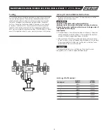
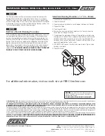
3 . After installation of backflow assembly and piping, attach drain funnel
to relief as shown, using self tapping screws provided in kit to join drain
funnel halves together, making sure that the slots in the drain funnel
are located over tabs on relief valve port .
NOTICE
Discharge of drain funnel is a slip fit design . Drain funnel was not
designed to, nor is it able to support drainpipe weight .
plaSTIC
MeTal
ValVe SIze
paRT nO.
paRT nO.
1
/
2
"
905358
905532
3
/
4
"
905358
905532
1"
905358
905532
1
1
/
4
"
905359
905533
1
1
/
2
"
905359
905533
2"
905359
905533
Air Gap Part Number


