2
PRESSURE VACUUM BREAKER
765 – Field Testing Procedure
Equipment Required For Test:
Sight Tube Test Kit (1" clear plastic Sight Tube about 40" long with appro-
priate fittings to attach to Testcocks of Vacuum Breaker.)
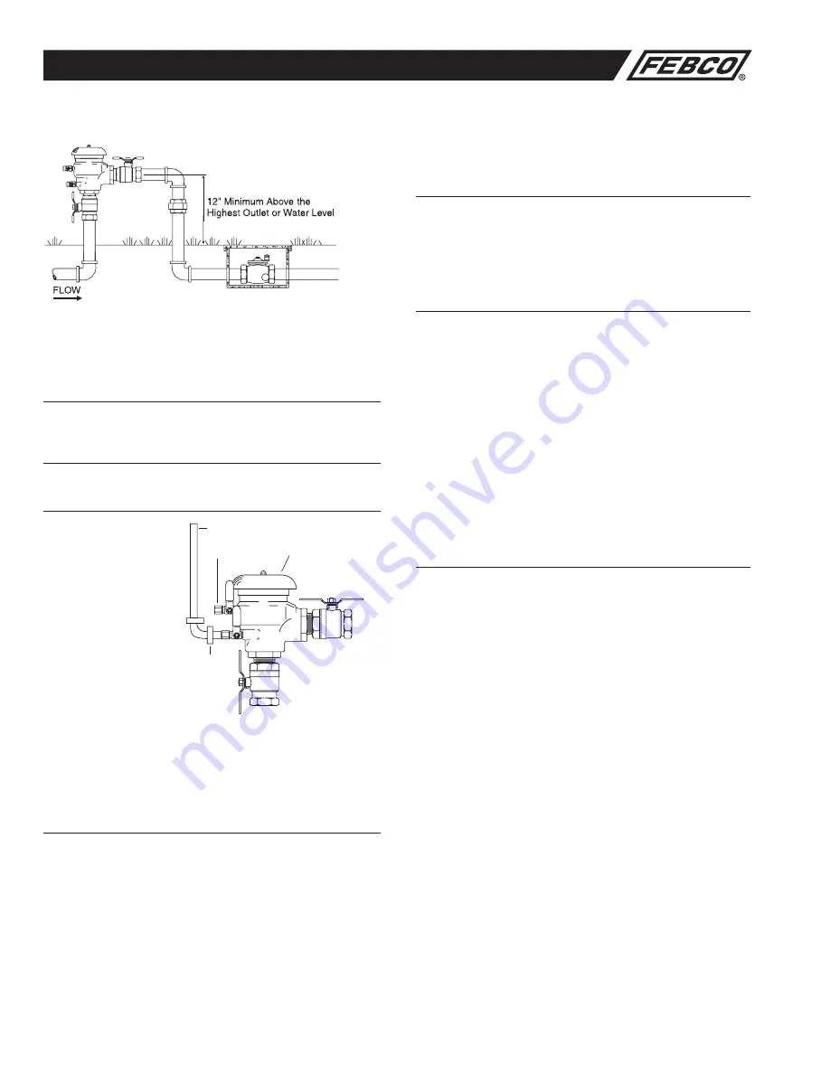
Purpose of Test: (see diagram)
To test the Air Inlet and the Check Valves for proper performance.
Test Air Inlet:
The Air Inlet should be
tested to verify opening
above 1psi.
1. Remove Canopy from
top of Vacuum Breaker to
expose Air Inlet.
2. Install Sight Tube at
Testcock #2.
3. Close Ball Valve B on
discharge side of Vacuum
Breaker.
4. Open Testcock #2 and fill
tube to about 30" above
poppet. Close Testcock
#2.
5. Close Ball Valve A on Inlet side of Vacuum Breaker.
6. Slowly open Testcock #2 watching poppet in Air Inlet. Poppet must
unseat. If the Air Inlet does not open, it is sticking and must be repaired.
Close Testcock #2 and remove sight tube.
Test Check Valve:
The Check Valve should be tested to hold against 1psi in the direction of
flow.
1. Install Sight Tube at Testcock #1.
2. Open Ball Valve A to allow unit to refill with water.
3. Open Testcock #1 and allow Sight Tube to fill about 30" above top of
unit, then close Testcock.
4. Close Ball Valve A. (Ball Valve B should already be closed.)
5. Open Testcock #1.
6. Open Testcock #2. Water may run from Testcock #2 initially, but should
not continue. The level of water in the Sight Tube may drop a little, but
should not drop below 28" above the Check Valve. (Centerline of the
Sight Tube
Testcock #2
Testcock #1
Ball Valve B
Ball Valve A
Canopy
Discharge Ball Valve.) If the level in the Sight Tube continues to drop
and water continues to run out of Testcock #2, the Check Valve is leak-
ing and should be repaired.
7. Close Testcocks #1 and #2.
Restore Operation:
1. Restore all Valves and Testcocks to their original positions and replace
Canopy.
Service Procedure
General service instructions applicable to all
sizes.
a. Rinse all parts with clean water prior to assembly.
b.
DO NOT USE ANY PIPE DOPE, OIL, GREASE OR SOLVENT ON
ANY PARTS
unless instructed to do so.
c. Do not force parts. Parts should fit freely together. Excess force may
cause damage and render the device inoperable.
d. Carefully inspect seals, seating surfaces, etc. for damage or debris.
e. Test unit after servicing to ensure proper operation.
f. Tighten canopy nut only until canopy cannot turn freely.
g. Rapidly open inlet ball valve to minimize spillage through the air vent.
Slowly open outlet ball valve.
h. Test unit to ensure proper operation.
i. Test unit after servicing to ensure proper operation.
j. Refer to applicable parts list and figures for visual aid information.
A. Model 765 -
1
/
2
" through 1
1
/
4
" sizes
1. Disassembly Bonnet/Poppet
a.
Close outlet ball valve then close inlet ball valve. Bleed residual pres-
sure by opening #2 testcock.
b. Remove canopy nut and canopy.
c.
Unscrew bonnet assembly from valve body by hand. (If neces-
sary, use appropriate size wrench on outside diameter of bonnet.
However, this may cause damage and require replacement of the
bonnet assembly.)
d. Remove poppet/seal assembly from body.
2. Check Valve Removal
a.
Evenly depress retaining bracket approximately 1/4", and rotate
bracket 90 degrees.
b. Remove the bracket, spring and check assembly.
3. Check Valve Seal Replacement
a.
Remove screw holding the guide, and lift the seal from its holder.
CAUTION:
Do not damage the guide legs or the guide pin of the
holder.
b.
Insert seal disc into holder, position guide in center of seal and
thread the retaining screw through the guide into the holder.
c.
Lightly tighten the screw to hold the guide from rotation.
CAUTION:
Over-tightening may cause distortion of the guide legs.
4. Assembly
To reassemble the device use the reverse procedure described above
along with the following special instructions.
a.
Position check assembly into valve body. Position spring into
recessed area on top side of check assembly.
NOTE:
In some cases
it may be easier to position the spring on the check assembly prior
to positioning in the valve body.
Typical Installations
Outside Installation (Side View)
IOM-F-765.indd 2
8/11/08 2:56:42 PM


