Fayat Group DYNAPAC CC425 Instruction Manual Download Page 58

Inspections and Operations 

50 


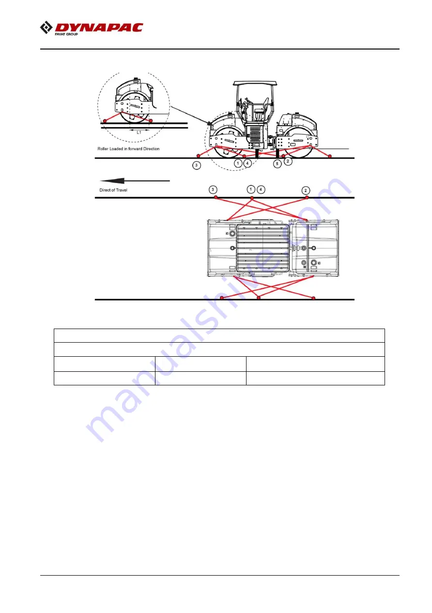
Figure 6-15: Securing the Vibratory Roller For Transport 


Table 6-1:Lashings' Permitted Distance 


The lashings' permitted distance interval in meters 

(1 - 4: Double lashings, LC at least 1.7 tonnes (1700 daN), STF 300 kg (300daN)) 

Double L

1

 - L

Double L

3

 - L


0,6 - 3,0 

0,1 - 3,0 


The distance L

1

 above is between points D and E. D is the projected point directly at right angles 

laterally in relation to the edge of the platform from the lashing mount C on the roller. E is the lashing 
mount at the edge of the platform. L

2


– L

3

 have a corresponding relationship. 


Summary of Contents for DYNAPAC CC425

Page 1: ...INSTRUCTION MANUAL Operating and Maintenance Vibratory rollers CC425 Engine KOEL 4R1190NA1 CEV Stage IV Serial number 10300616CME010845 4812332527_A June 2021 K ...

Page 2: ...d responsible for any damages caused by unauthorized modification of the machine and its associated equipment The manufacturer is not liable for damages caused by inappropriate use Damage that occurs as a result of substandard repairs as well as injury to personnel or damage to equipment that is attributable to older un repaired damage is not covered by the customer warranty policy Always refer to...

Page 3: ...on 9 Brake system 9 Secondary Parking Brake 9 Steering System 9 Roller Applications 9 Designated Applications 9 Non Designated Applications 9 Section 2 Safety First 2 1 General Information 11 Warnings and Cautions 12 Personnel Protective Equipment 12 Tools and Equipment 12 Operating Safety 13 Before Starting the Engine 13 Starting the Roller 13 Parking the Roller 13 Driving Near Edges 13 Slopes 14...

Page 4: ... Battery Handling 18 Jump Starting 19 Section 4 Specifications 4 1 Weight and Dimensions 21 Diesel Engine 22 Fluid Volume 23 Working Capacity 23 Hydraulic System 23 Section 5 Operation Controls 5 1 Instruments and Controls 25 Functional description Keypad 26 Starter Switch 27 Speed selector 27 Work Transport mode 27 Emergency Stop 28 Forward Reverse FNR Lever 28 Sprinkler Switch 28 Seat Buzzer 28 ...

Page 5: ...otification Symbols 34 Section 6 Inspections and Operations 6 1 General Information 37 General Checks 37 Operator Areas 37 Check Engine Oil Level 38 Check Engine Coolant Level 38 Check Fuel Level 39 Check Batteries 39 Verify the Controls 39 6 2 Before Starting the Engine 40 Seat Standard Adjustment 40 Check the Instruments and Lamps 41 Interlock 41 6 3 Operating the Roller 42 Operation 42 Vibratio...

Page 6: ...formation 53 7 2 Maintenance Schedule 54 Maintenance Schedule Information 54 7 3 Refill Capacities Lubricants 57 General Information 57 Lubrication Chart 58 Refill Capacities 58 7 4 Standard Torque Values 60 Head Markings 60 Recommended Torques 60 7 5 Maintenance as Required 62 Service as Required 62 Clean the Roller 62 Loose Bolted Connections 62 Air Cleaners 62 Connections and Ducts 62 Air Clean...

Page 7: ...r Tank 67 Fixed scrapper 67 Brakes 68 Sprinkler System 68 7 6 Lubrication and Filters 69 Hydraulic Reservoir 69 Check Hydraulic Oil Level 69 Steering Cylinder and Steering Joint 70 Drum Oil Level 70 Check Drum Gear Oil Level 71 Controls 71 Housekeeping 71 ...

Page 8: ...This page is intentionally blank ...

Page 9: ...ropriate information needed to Safely operate the CC425 roller while achieving optimum production Understand the operating principal of each system associated with the CC425 roller React effectively and safely to emergency and alarm conditions Perform the necessary pre operational and post operational checks on the roller If any part of this manual cannot be understood contact the supervisor or lo...

Page 10: ...lting the shipment documents If the goods are damaged or if parts are missing inform the freight agent and raise a complaint against it Identification Data An exact description of the model type and the serial number of the roller facilitates fast and efficient response from our parts and service support operations Provide the model type and serial number while contacting the local Dynapac service...

Page 11: ... digit number which provides information about manufacturer family model check letter no coding production unit and serial number Figure 1 2 Location PIN A Serial number The pin number is punched on top right side of the side plate Figure 1 3 Location PIN A Pin number A A Manufacturer B Family Model C Check letter D No coding E Production unit F Serial number ...

Page 12: ...provides model identification and other important data about the engine Refer to the engine operation and maintenance manual for further information on the identification information Have the following engine data available when communicating with an authorized repair location or engine dealer The data on the engine identification plate is mandatory when sourcing service parts Engine serial number...

Page 13: ...mum performance on a wide range of applications and site requirements the roller is equipped with Diesel engine Electrical system Propulsion system transmission Brake system Secondary parking brake Steering system Canopy Identification of Major Components Figure 1 5 Major Components Right Side A Rear light E Mirror J Vibration motor B Water tank F Steering console K ROC C Hydraulic tank G Fuel tan...

Page 14: ...ight J Rear light N Cylinder B Water tank K Scraper P Drum D Seat L Vibration motor Q Propulsion motor E Platform M Steering hitch R Sprinkler pump F Fuel tank Diesel Engine The roller is equipped with the water cooled straight four cylinder BS IV diesel engine R ...

Page 15: ... 30A Mini Relay F Battery Disconnector Switch C 100A Starter Relay G 30A Engine ECU fuse A Battery disconnector Main and Light Fuses The main fuse and light fuse are placed near to a 100A starter relay on battery disconnector bracket Table 1 1 Placement of Fuses F10 Main fuse 40 A F11 Light fuse 40 A F13 Engine ECU fuse 30 A Component Rating Battery 12V 150AH Alternator 12V 90amps Starter 12V 2 7k...

Page 16: ...C Engine ECU F Starter Relay D Battery disconnector switch G Mini Relay H Mini Relay I Mini Relay Sl No Function Amperage 1 Main fuse Ignition emergency Parking brake vibration Drum selection 15 A 2 Working light relay Dyn link Ignition terminal 15 A 3 Sprinkler pump USB charger 10 A 4 Rotating beacon relay 10 A 5 Drum Speed Back up alarm switch 15 A 6 Engine Diagnostic tool 10 A 7 ECU battery ve ...

Page 17: ...ler is built in accordance with international standards and recognized safety rules Nevertheless misuse may constitute a risk to the life and limb of the user or third parties and may cause damage to the roller or other material property The roller must be used in accordance with its designated use as described in this manual The roller must only be operated by trained safety conscious persons who...

Page 18: ...This page is intentionaly left blank ...

Page 19: ...theory and practices During operation of this roller local safety and fire protection standards must be observed Do not use the roller in need of adjustment or repair Mount and dismount the roller when it is stationary Use the intended grips and rails Always use the three point grip both feet and one hand or one foot and both hands when mounting or dismounting the roller Do not jump on or off a mo...

Page 20: ...ller Dynapac cannot be held responsible for any accidents incidents or damage to persons or property that are related to the use of modified roller Personnel Protective Equipment Anyone working around the roller must wear approved safety equipment safety shoes or protective footwear safety glasses hearing protection hard hat gloves respirator and the like when operating or maintaining the roller W...

Page 21: ...gine check that all the gear controls are in neutral position Always inspect the motor before and after starting Check all the safety devices Report any defects immediately Listen for unusual noises Engage hydraulic controls slowly in cold weather to avoid shock loading Parking the Roller Select the level and hard ground If necessary to park on the slope block the front of the drums on the downsid...

Page 22: ... operating temperature of hydraulic oil is hot enough to cause serious burns Use precautions when working on any hot fluid lines or changing filters Hot oil or components can burn Avoid contact with hot oil or components Do not allow used oil to drain into the ground Dispose the used oil properly in accordance with the local guidelines Cylinder Repairs or Replacement When repairing cylinders make ...

Page 23: ...eels of the transport vehicle when loading the roller Position the roller on the transport vehicle centered from side to side and use proper chock blocks in front and rear of the tracks Secure the roller to the deck of the transport vehicle with adequate chains or cables and blocks to meet local regulations When moving the roller on public access roads obey all traffic regulations and make sure th...

Page 24: ...l List Decal Message Location Warning Crush zone Quantity 2 Engine frame left and right bottom side Warning Rotating engine components Quantity1 Engine frame left top side Warning Hot surfaces Quantity 1 Engine frame front center side on grill Warning Instruction manual Quantity 1 Center of cancol cover below steering wheel Warning Risk of crushing Quantity 2 Front left and right side plate Warnin...

Page 25: ...F Cold start in the range of 4 C to 15 C 39 2 F to 5 F Higher Ambient Temperatures For operation of the roller at higher ambient temperatures however maximum 50 C 122 F The diesel engine can be run at this temperature using normal oil Hydraulic system mineral oil Dynapac Hydraulic 300 or similar Lower Ambient Temperature Freeze Risk Make sure that the watering system is empty drained of water spri...

Page 26: ... surrounding conditions N o t e Specifications represented are calculated values at 100 efficiency Operator life may be endangered if the following is not complied with Do not add attachments to the roller that intrude into the operator protective area reduce visibility restrict emergency exits or add weight exceeding certification weight See the operation manual or contact the dealer for complete...

Page 27: ...the roller with the flat battery 5 Start the engine on the power providing roller Let it run for a while Now try to start the other roller 6 Disconnect the cables in the reverse order Figure 3 1 Jump Starting A Battery s positive terminal one B Battery s positive terminal two C Battery s negative terminal three D Battery s negative terminal four Fig Ignition key battery disconnector 1 Ignition key...

Page 28: ...This page is intentionaly left blank ...

Page 29: ...mensions Side View Table 4 1 Weight and Dimensions Side View Wheel base 2785 mm 109 6 in Length 4340 mm 170 9 in Height with canopy 3140 mm 123 6 in Height without canopy 2460 mm 96 9 in Thickness 17 mm 0 7 in Operating mass 9200 kg 20282 53lbs Max Operating mass 9600 kg 21164 38lbs ...

Page 30: ...eight and Dimensions Top View Turning radius outer 6500 mm 255 9 in Turning radius inner 4800 mm 188 9 in Drum width 1690 mm 66 5 in Steering angle 28 degree Diesel Engine Table 4 3 Diesel Engine Engine Model HP kW rpm KOEL 4R1190NA1 BSIV 74 5HP 54 8kW 2200 rpm ...

Page 31: ... Working Capacity Static linear load front 28 4 kg cm Static linear load rear 26 0 kg cm Amplitude 0 9 mm 0 4 mm 0 036 0 01 in Vibration frequency 36 Hz 54 Hz Centrifugal force 130 kN 60 kN Hydraulic System Table 4 6 Hydraulic System Opening pressure Absolute pressure MPa Bar Psi Drive system 35 0 350 5076 3 Vibration system 35 0 350 5076 3 Steering system 17 5 175 2538 Charge pressure 2 5 25 365 ...

Page 32: ...This page is intentionaly left blank ...

Page 33: ...n the consoles and around the roller The operator console is located in front of the operator seat under the steering wheel The slim profile and quick opening side panels provide easy access for maintenance and service Figure 5 1 CC425 Console A High Beam H Parking brake On Off B Driving lights J Keypad C Dual Speed D Hazard warning lights E Display F Direction indicators G Emergency ...

Page 34: ...hts of canopy LED OFF LED LEFT Working lights ON Red Sprinkler Manual Auto LED LEFT Sprinkler manual Red LED RIGHT Sprinkler auto Red Sprinkler Timer LED LEFT Sprinkler spray low Red LED CENTER Sprinkler spray medium Red LED RIGHT Sprinkler spray high Red Engine speed selector LED LEFT Speed low Red LED RIGHT Speed High Red Amplitude hight low Working mode Rotating beacon Not Applicable Working li...

Page 35: ...osition 30 Start position to supply power to the instruments and controls 2 On position 15 Hold position 50 a Starter motor activation Speed selector The Speed selector regulates the speed of the engine In the ON LED Left position the engine idles and in the ON LED Right position the engine runs at full speed Figure 5 3 Speed selector A Speed selector Work Transport mode The 1st number button is u...

Page 36: ...s auto mode is activated with red illumination in right side button Machine running condition water flow comes on drum 6th Button for sprinkler timer to adjust water spray in three mode A Emergency stop button Forward Reverse FNR Lever The direction of travel and speed of the roller is regulated with the forward reverse FNR lever The roller speed increases or decreases in proportion to the lever p...

Page 37: ...m selector the vibration is activated in the following places Left side button Activates vibration for front drum Right side button Activates vibration for rear drum Figure 5 11 Drum Selector Switch Fuse Box The fuse box is located on the control column that contains the fuses for the electrical system Fuses protect the electrical components from short circuit damage Refer to electrical system for...

Page 38: ...such as roller that is stopped or moving slower than the rate of the traffic Depress the switch to turn on the rotating beacon Figure 5 15 Rotating Beacon Switch Direction Indicator Switch The direction indicators are blinking lamps mounted near the left and right front and rear corners of the roller Depress the Direction indicator switch to either left or right to turn on the left or right indica...

Page 39: ...osition F Forward A left arrow is shown in front of F on the display R Reverse A right arrow is shown after R on the display Hour meter An icon hour glass is shown on the left hand side of the display for machine hours The number of hours is shown to the right of the icon 3 Fuel level The fuel level is indicated as a no of lines of on the bar to the right of the display Once the first fuel bar is ...

Page 40: ...elow conditions 1 Select button of display in front of AVC it will appear on display as shown in beside encircled snap 2 Activate work mode from Keypad 3 Select either low or high amplitude from Keypad 4 Switch ON Vibration Sw on FNR lever only once 5 Whenever machine comes in neutrl vibration will stops whenever it moves away from neutral vibration will automatically starts This time you dont nee...

Page 41: ...ttery voltage is low i e 12 5V the charging symbol should come with Orange red alert as per beside snap Diesel engine lubricating oil pressure indicator When engine oil press Level is low immediately symbol should come with RED colour alert Diesel engine Coolant temperature indicator When engine temp high immediately symbol should come with RED colour alert Low fuel level indicator The lamp illumi...

Page 42: ...ion as full It s solid or dark when tank is full 2 It s hollow or blank when tank is empty less fuel Hour meter Ensure hour meter should clocked every after 1 hour with change in hour digits Glow plug indicator Glow Plug indicator illuminates momentarily for approximately 5 seconds once ignition is switched on When glow plug is active immediately the glow plug LED should be on Air filter indicator...

Page 43: ... on display Enabling Vibration in transport mode When operator tries to enable the vibration from the transport mode display will show this pop up Driver away from seat When operator stands from seat while machine is moving display will show this pop up Water in Fuel When water detected in fuel immediately symbol should come with yellow colour alert Malfunction Indicator During malfunction indicat...

Page 44: ...ver FNR lever comes in correct neutral position Symbolic representation of Vibration ON in low amplitude Switched ON vibration in low amplitude check symbol as per beside snap with single curve below drum this needs to be checked whenever machine running in Vibration low mode only Symbolic representation of Vibration ON in high amplitude Switched ON vibration in high amplitude check symbol as per ...

Page 45: ...erturning or when loading onto a transporter where there is a risk of overturning Always use a spotter General Checks Do general checks for any wear and tear on the roller Check for broken or cracked welds loose or missing bolts broken or inoperative gauges or any other irregularities which could lead to more costly breakdowns Check oil levels before starting the roller Check all bolted assemblies...

Page 46: ...f the engine and allow to cool before removing the radiator cap Remove cap slowly to relieve pressure Avoid contact with steam or escaping fluid Removing the radiator cap on a hot radiator can cause scalding coolant to spray out and burn the body badly If the engine has been in operation within the previous 30 minutes be very careful in removing the radiator cap Protect face hands and arms against...

Page 47: ...k to get emptied otherwise the entire fuel system will require bleeding 3 If the fuel level is low add clean filtered fuel 4 Fill the tank with the correct grade of fuel Refer to Lubrication Table for more fuel details Check Batteries Batteries contain an acid and can cause injury Battery fumes can ignite and explode Do not smoke when observing battery fluid level Skin and eye contact with battery...

Page 48: ...6 2 Battery Disconnector A Battery disconnecter 3 Check for warnings on the controls 4 Start the engine only from the operator position If any controls instruments or devices do not function correctly report the defects to the proper personnel Defects must be corrected before starting and operating the roller Seat Standard Adjustment Adjust the operator seat to the comfortable position so that the...

Page 49: ...ngaged 1 Turn on the switch 2 Check that the warning lamps in the warning panel illuminates 3 Set the sprinkler switch to the operating position and check for the system is functioning Interlock The roller is equipped with interlock The diesel engine switches off after 10 seconds if the operator gets off the seat during tramming If the operator is not seated during tramming a buzzer goes on until ...

Page 50: ...Figure 6 4 Operator Consoles A Emergency stop C Ignition switch B FNR lever D Engine RPM 3 Make sure the Emergency stop button is not activated 4 The FNR lever must be in neutral position 5 The Parking brake switch must be in the engaged condition 6 Make sure the Engine RPM switch is turned to low position Figure 6 5 Engine RPM Figure Engine RPM 7 Set the vibration switch for high low vibration po...

Page 51: ...nd 2 2 Vibration is activated by using theswitch in the FNR Lever In the Left button the vibration is activated on front drum In the Right button the vibration is activated for rear drum In both button the vibration is activated for front and rear drums Braking Normal Braking 1 Turn off the vibration by pressing the Vibration control button on the FNR lever 2 Set the FNR lever to the neutral posit...

Page 52: ...rake button to activate the parking brake Always activate the parking brake before leaving the roller N o t e If the roller must be parked on a sloping surface chock the drums with wedges to prevent any movement 5 Check instruments and warning lamps to see if any faults are indicated Switch off all lights and other electrical functions 6 Turn the Starter switch to the off position to stop the engi...

Page 53: ... the locking arm and locking lug and secure the stud in position with the locking pin N o t e Remember to refit the lock bar in its holder after operation Figure 6 8 Locking the articulation A Lock bar Lifting the Roller Use a crane forklift to lift the equipment Pay attention when lifting and balancing the equipment Seek a person to guide the way when lifting and moving the equipment An experienc...

Page 54: ...r can be towed The roller can roll free if drum is not blocked Follow the recommendations below to properly perform the towing procedure Make sure to block the drums of the roller and reapply the emergency brake system before disconnecting from the towing vehicle N o t e Maximum towing speed is 2 mph 3 Kmph Towing The roller can be moved up to 300 meters 1 000 ft using the instructions below N o t...

Page 55: ...en Step C Knob 3 5 Operate the lever for 10 to 12 times to manually release the brake Figure 6 12 Brake Release Step D Lever Engaging the Brakes 1 Turn knob 3 counter clockwise after towing 2 Tighten the Allen screw 2 to original position and then tighten nut 3 Figure 6 13 Towing ...

Page 56: ...r clearance flags lights and warning signs including the slow moving vehicle emblem are properly displayed Know your approximate stopping distance at any given speed Never turn corners at excessive speeds Look in all directions before reversing the direction of travel Operator Checklist Make sure to know the vehicle and its equipment and how to use it safely See that mirrors and lights are clean a...

Page 57: ...ransport Figure 6 14 Securing for Loading A Lashing wire B Chocks 1 Chock the drums securely 2 Support the drum frame firmly to prevent overloading of the rubber suspension of the drum 3 Anchor the roller securely with lashing wire at all the four corners ...

Page 58: ...uble lashings LC at least 1 7 tonnes 1700 daN STF 300 kg 300daN Double L1 L2 Double L3 L4 0 6 3 0 0 1 3 0 The distance L1 above is between points D and E D is the projected point directly at right angles laterally in relation to the edge of the platform from the lashing mount C on the roller E is the lashing mount at the edge of the platform L2 L3 have a corresponding relationship ...

Page 59: ... and oil cooler clean and free of accumulated dirt High Altitude Conditions Be aware that engine power will be reduced Keep cooling fins on radiator and oil cooler clean and free of accumulated dirt N o t e Contact the engine dealer for fuel system adjustment before working on high altitude condition Long term Parking Observe the following when storing the roller for short periods of time Remove t...

Page 60: ...se the steering cylinder piston with conservation grease Grease the hinges on the doors to the engine compartment and the cab Grease both ends of the forward reverse control bright parts Change all lubricants and fluids that may have deteriorated with use Replace and secure all weatherproof covers Figure 6 16 Long Term Parking ...

Page 61: ...ing operational hints are observed Do not speed the engine when it is cold Always chock the drum if there is a possibility of uncontrolled movement Do not lubricate the roller while the engine is running Always perform safety checks prior to starting and using the roller Always operate the roller at the full engine power Never propel or stop the roller on a slope or surface that could possibly col...

Page 62: ...t maintenance than specified is necessary Table 7 1 Maintenance Daily Every 10 Hours Description Action Lubrication Engine oil Check level Engine primary air filter Check Vacuum Indicator change it if shows Chocking Radiator coolant Check level Hydraulic oil Check level Greasing Grease See lubrication chart Table 7 2 Maintenance at First 50 Hours Description Action Lubrication Engine oil filter el...

Page 63: ...ver Check for any leakage Engine V Belt Change See engine manual Fuel tank Drain and clean Table 7 6 Maintenance at 1 000 Hours One Year Description Action Lubrication Engine oil filter element Change See engine manual Engine oil Change See engine manual Pre fuel filter element Change See engine manual Main fuel filter Change See engine manual Engine primary air filter Change See engine manual Saf...

Page 64: ...ine oil Change See engine manual Pre fuel filter element Change See engine manual Main fuel filter Change See engine manual Engine primary air filter Change Safety filter Change Valve cover gasket Check Engine Drive V belt Change Hydraulic oil Change Hydraulic oil filter element Change Drum oil Change Fuel tank Drain and clean Drum gear oil Change ...

Page 65: ...check points the oil levels are to be at the bottom edge of the check port All the grease fittings are SAE standard unless otherwise indicated Grease the non sealed fittings until the grease is seen extruding from the fitting One ounce 28 grams of EP MPG equals one pump on a standard one pound 0 45 kg grease gun Over lubrication on the non sealed fittings will not harm the fittings or components b...

Page 66: ...r oil 400 5L 1 3 gallons Refill Capacities The following fluid capacities are provided for the servicing personnel who must perform roller maintenance in the remote locations where complete shop facilities and resources are not available These capacities will give the servicing personnel an approximation of the fluid capacities of the components to be serviced Always use the specified method to ch...

Page 67: ...nance Symbols Symbol Description Symbol Description Engine oil level Air filter Engine oil filter Battery Hydraulic reservoir level Sprinkler Hydraulic fluid filter Sprinkler water Drum oil level Recycling Lubrication oil Fuel filter ...

Page 68: ...ng pages list the recommended tightening torques for the various size bolts used for the roller Proper torque specifications should be used at all times Recommended Torques This page lists the recommended tightening torques in foot pounds ft lb for the various size bolts and nuts that are used Proper torque specifications should be used at all times Dry means clean dry threads and lube means a lig...

Page 69: ...ric coarse thread zinc treated Dacromet GEOMET 10 9 Oiled 10 9 Dry 12 9 Oiled 12 9 Dry M6 120 150 146 183 M8 28 36 34 43 M10 56 70 68 86 M12 98 124 117 147 M14 156 196 187 234 M16 240 304 290 360 M20 470 585 560 698 M22 626 786 752 944 M24 800 1010 960 1215 M30 1580 1990 1900 2360 Bolt dimensions M16 PN 902889 Strength class 10 9 Tightening torque 192 Nm torque class 2 Dacromet treated Maintenance...

Page 70: ...ner ducts a Check intake for accumulation of debris that could restrict air flow b Check the air cleaner mounting hardware for security c Check all hoses for cracks chafing or deterioration and replace at the first sign of probable failure Loose Bolted Connections If any loose nuts or bolts are found during the frequent walk around and the daily inspections make sure they are properly torqued Refe...

Page 71: ... When the choking air filter indicator illuminates do the following maintenance steps 1 Unclip the clamps holding the main filter 2 Carefully withdraw the main filter N o t e Do not clean the air filter until the indicator illuminates on the control panel Cleaning the filter when there is no indication is not recommended N o t e Make sure new elements arrive enclosed in plastic or in a protective ...

Page 72: ... Clean the air filter element from inside to outside using compressed air N o t e Replace air filter element after two cleaning interval Air Circulation Check that the engine has free circulation of cooling air through the grille in the engine compartment Figure 7 5 Air Circulation A Cooling air grille Hose and Clamps 1 Periodic clamping bolts re tightening is necessary due to cold flow present in...

Page 73: ...g battery maintenance must be carried out as part of the 250 hour routine maintenance schedule Batteries contain an acid and can cause injury Skin and eye contact with battery fluid can cause injury Avoid skin and eye contact with battery fluid If contact occurs flush area immediately with water Battery fumes can ignite and explode Do not smoke when observing battery fluid level N o t e When disco...

Page 74: ...Refuel the tank every day before starting the roller 1 Unscrew the lockable tank cap 2 Fill diesel fuel to the lower edge of the filler pipe Check fuel tanks and fuel lines for possible leaks Because of the potential fire hazard leaks must be corrected as soon as they are spotted Fuel is flammable May cause serious injury or death Shut off the engine extinguish all open flames and do not smoke whi...

Page 75: ...caping from the radiator can burn Inhibitor contains alkali Avoid contact with skin and eyes Wear protective gloves and eye glasses Always shut off the engine and allow it to cool down before removing the radiator cap Remove the radiator cap slowly to relieve pressure Avoid contact with steam or escaping fluid Fixed Scrapers Make sure that the scrapers are undamaged Adjust the scrapers so that the...

Page 76: ...se lever in neutral Pull out the emergency stop Start the engine The roller is now ready for operation Sprinkler System Start the sprinkler system and make sure that nozzles are clogged If necessary clean clogged nozzles and the coarse filter located by the water pump The sprinkler system should be drained if there is a risk of freezing Wear protective eye glases when working with compressed air D...

Page 77: ...pecifications if level is too low N o t e Dirt in the hydraulic system will lead to premature component failure A clean contaminant free system is extremely important for the roller to function properly Check Hydraulic Oil Level If the hydraulic oil level is low add hydraulic oil 1 Level the roller 2 Check the reservoir oil level by viewing the sight gauge Verify that fluid level is near the maxim...

Page 78: ...trates into the bearing If grease does not penetrate into bearings it may be necessary to relieve the articulation joint with a jack while repeating the greasing process Figure 7 15 Greasing A Grease nipple Drum Oil Level 1 Run the roller slowly until the oil plug is opposite to one of the inspection holes 2 Unscrew the plug and check that the oil level reaches up to the bottom of the hole Top up ...

Page 79: ...or platform 2 Check the tower feed installation for debris buildup around the sheaves 3 Thoroughly wash all fittings caps plugs and the like with a nonflammable nontoxic cleaning solution before servicing to prevent dirt from entering while performing the service N o t e Protect all electrical components and control panels against entry of water or steam when using high pressure cleaning methods C...

Page 80: ...This page is intentionaly left blank ...

Page 81: ...www dynapac com Dynapac Road Construction Equipment India Pvt Ltd Plot no 01 Gat no 163 168 Alandi Markal road Village Fulgaon Taluka Haveli Dist Pune 412216 India ...

Reviews: