40
4 Functional Description
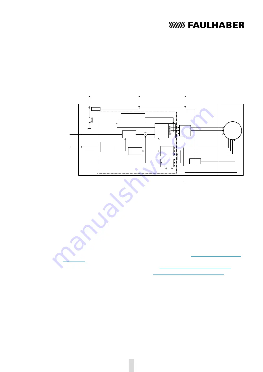
4.4 Motor with SC speed controller
Block diagram
DIR
Rotational direction input
Evaluation
rotational
direction
U
nsoll
n
soll
0 – 10 V DC
Setpoint input
Digital output
FG
22 k
Ω
Electronics supply
U
p
Motor supply
U
mot
GND
MOSFET
Power
output
stage
Protection function:
Overtemperature
Microcontroller
PI velocity
controller
Speed
calculation
Armature
position
calculation
(t)
I²t current
limitation
U
a
3 Phase
PWM
block
commutator
5 V-Control
BL-Motor
Phase A
Phase B
Phase C
Hall sensor A
Hall sensor B
Hall sensor C
VCC
+5 V
Signal GND
I
ist
RM
Motor
model
k
E
Setting options
Pure 2-Quadrant operation without active braking option.
If problems occur during operation with the braking function in the default setting it can be
deactivated.
Filtering (averaging) of the Hall sensor signals.
If problems occur with the default setting the time of a complete electrical (half) motor revolu-
tion is evaluated to obtain a continuous speed signal. This can cause instable motor running at
low speeds as the control dynamics worsen.
Configuration of the digital output as error output.
Frequency output can be configured to 6 or 2 pulses per revolution.
Target velocity value via PWM signal at the target velocity input. See
.
Operation with fixed speed (fixed speed mode). See
Chapter 4.4.3 “Special configurations”
.
Operation as voltage controller (volt mode). See


